PM2.5 particulates are becoming a major concern as air-borne contaminants. These micro particles with a diameter of less than 3µm have become subject to new health standards, as when they are inhaled they are too small to be discharged from the lungs and if they remain there for a long time can increase the risk of lung cancer.

Humans breathe a whole lot of air – almost 1500 litres each day. As a result, about 70% of the hazardous substances absorbed by the body comes via the lungs. Usually, even if microparticles stick to the air sacs of the lungs, they are dissolved through the normal functions of the lungs. However, substances such as asbestos or silica are materially stable and do not dissolve in the air sacs of the lungs. It is considered that these substances accumulating in the lungs can lead to a possible risk of cancer. Further, it has also become quite clear that near main trunk roads, vehicle exhaust fumes containing active polluting substances further increase the risk of lung cancer.

While the issue of PM2.5 is very topical, contaminants which are generated far away and drift in the air for a long time do not remain active and are therefore not a serious problem. Rather, the most serious concern is air pollution generated nearby. To be specific, this could come from exhaust fumes from nearby roads, asbestos, silica or lead from soil which is blown up in the wind. There should also be concern in special environments such as pharmaceutical or medical firms that deal with highly potent compounds such as anti-cancer drugs or sites that treat nanoparticles, typified by carbon nanotubes, which are recently drawing attention as new materials.

In particular, within these premises that deal with such hazardous substances, human exposure during synthesizing, production, measurement, separation, collection, etc. is a major issue. The people who manufacture, research and analyze these substances are being placed in the most dangerous circumstances in the course of their duties.

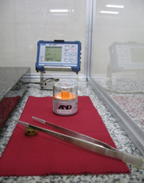
In the measurement of PM2.5 particulates, air is suctioned in from outdoors and passed through a filter. An electronic balance is then used to measure the total amount of microparticles caught in the filter. From news reports such as those we hear from Beijing, with PM2.5 particulates exceeding 300 micrograms per cubic meter of air, we can understand that pollution levels of PM2.5 are determined through weight measurements. Incidentally, the measurement environment for these PM2.5 particulates is subject to extreme restrictions. In order to stabilize measurement with the analytical balance and reduce errors due to moisture absorption, etc., it is stipulated that a measurement environment of 21.5 ±1.5°C and humidity of 35 ±5% must be realized. Also, in order to effectively trap microparticles, a fluorinated filter which can become statically charged very easily and a balance with electrostatic elimination capability are required as well.

At first glance these standards seem quite appropriate, but in order to control the temperature and humidity of a room with balances installed at constant levels, strong breezes are required which will agitate a balance and make stable measurement very difficult. Further, these strong breezes required for controlling temperature and humidity will also cause the hazardous substances trapped in the filters to be stirred up into the air, possibly being inhaled by the researchers conducting the measurement and posing a significant problem. These issues of exposure apply not only to PM2.5 particulates, but all the other hazardous substances mentioned above.

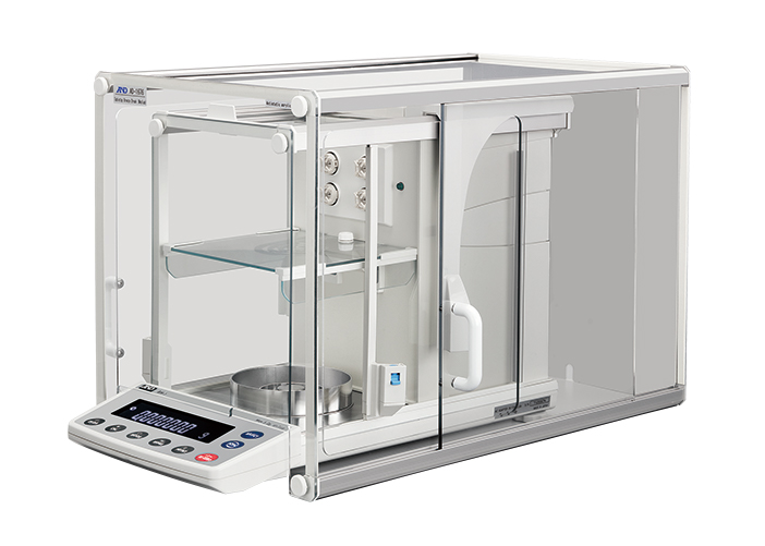
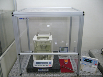
Meanwhile, in recent years devices developed in Europe called balances enclosures, which can seal off hazardous substances, have been drawing a lot of attention as a solution to this problem. Balance enclosures provide the dual functionality of containing these dangerous microparticles and also stabilizing the weight display of the balance. When comparing its capabilities to completely sealed glove boxes or fume hoods which can only perform forced exhaust, the balance enclosure differs in guaranteeing that hazardous microparticles can be easily sealed. Then it occurred to me that creating a measurement environment for PM2.5 particulates by drawing on these features of enclosures might also resolve the problem of exposure to hazardous substances. The remaining problem is therefore how to control temperature and humidity of the air contained by the enclosure while measuring.

Achieving the required measurement environment for PM2.5 particulates for the entire room where an analytical balance is installed requires significant initial facility setup costs, as well as large regular running costs. Also, as mentioned earlier, there is a problem of researchers being exposed to hazardous substances, and it is clear that the balance display inevitably becomes unstable in the end. Further, the high initial cost of the large-scale facilities like those currently being introduced to prefectural institutes for environmental studies is making PM2.5 research very difficult for private enterprises which do not have access to public funds.

Considering these circumstances, I wondered if there wasn’t a possible method for managing the internal humidity and temperature of such a balance enclosure while also keeping the safety functionality of the devices. At that time, the fact that we were manufacturing balance enclosures domestically as an original product suddenly had added merit to us. That is because I conceived the idea that the problems mentioned above could be solved by connecting a balance enclosure to a temperature and humidity controller, as well connecting to a high precision filter unit and then connecting the temperature and humidity controller to the outlet of the filter unit.

Combining these three devices – balance enclosure, temperature and humidity controller and filter unit – is quite simple, but is rendered meaningless when the circulating air inside the unit escapes through the opening section in the front made for operating the measurement apparatus inside. In order to solve this problem, we performed testing for the air’s flow path. As a result, we found that allowing air to flow in from the top of the enclosure, and after stopping this flow with a baffle positioned at the top, allowing the air to be exhausted through the side of the enclosure will successfully let air flow in through the opening at the front. Incidentally, a baffle is a type of control plate configured to control the flow of fluids such as air. The proposed features of this system are not yet included in similar systems either in Japan or overseas, so the assemblage and internal framework of the system was lodged as a patent.

We believe the weighing system proposed here will be widely used for creating a measurement environment for hazardous substances, including PM2.5 particulates, that can be offered at a low price with no further installation work required, which also allows for stable measurement and fully protects the operator from any hazardous substances being measured.

The model below provides a visualization of the basic components of the system.

Weighing system for hazardous substances

I have been publishing these Development Stories for over three years now. Upon reflection, it feels that there is a great number of technical terms appearing in each installment, with the details often quite hard to understand. I have therefore added a yet untold story to this episode. About eight years ago, I was talking to a contractor who was building one of the core components of our balances using a special resin. What he told me then was that people who build or develop new things could be considered technological wizards who can magically pull marvelous new creations out of a hat. This component he was building was designed featuring innovative structure and materials that were world firsts in the balance field. At first, however, with all the many resin cast contractors I had met up to that time, after showing them the plans and discussing the design with them, the answer was always “it’s impossible”. I therefore had a big favor to ask of this developer who I was meeting for the first time. While it was extremely tough for him, the design and production of the part was finally completed and it went on to be successfully incorporated into all further A&D balances resulting in a dramatic improvement in the basic functionality of balances.

Returning to my earlier discussion, at first I did not understand the meaning of the comment that developers are “technological wizards”. What he was getting at was that developing something that did not previously exist in this world is an incredibly creative process that requires a bit of special magic. Prior to that meeting, I was already making it my credo as a developer to realize products that surpass competitors’ in functionality and cost effectiveness. But after being called a wizard I came to think from then onwards that, if I consider my role as a developer in an industrial nation, I should refrain from simply producing for the market a reduced cost version of previously available products and try aiming for some real magic. From that time onwards, if I was not working on a new product where there is nothing similar existing in the market yet, or the product is not targeted toward a special market, I resolved to at the very least add some new value or function to a product when I am performing my development work.

Actually, from around that time onwards, considering products which are completely new creations, A&D has released various products such as a pipette leak tester, weighing data logger, environment logger, tuning fork vibro rheometer and balance analyzer. These products have not been as easy to sell as our other, more traditional types of products in Japan. This may be because A&D is perhaps weak in addressing sales routes for products where detailed explanations are required, but we could also say that Japanese are not, particularly in relation to industrial products, open to trying unique new products and instead wait for new developments to be accepted overseas before making their way to Japan. On the basis of that supposition, I have a fear that our new weighing system for hazardous substances will not be easily sold in the Japanese market as a domestic product. However, whether a new product sells well or doesn’t, as a person engaged in new product development and technology in an industrialized nation, in the end I am still fully committed to continuing the development of unique and exciting new products.

In the previous Development Story, the results of market research into the micropipette market were discussed. However, as this occurred before application for intellectual property rights it was not possible to discuss the details of the technology involved in this new product. In this episode I will explain the aims of the development of the MPA Series of electronic pipettes and the functionality we devised to actually realize those aims.

It has been more than half a century since manual pipettes reached their present form. This could be interpreted as meaning manual pipettes that are presently sold in the market are completely perfected pieces of research equipment.

Modern day pipettes firstly move their pistons by the push of a button. They then work using the method of aspirating liquids due to the difference in air pressure created by the movement of the pistons. That is why they are called the air displacement type. These principles are highly praised as a means for measuring and moving liquids both safely and without contamination.

Presently in Japan, manual pipettes for aspirating and dispensing liquids account for 90% of the market, with the remaining 10% coming from electronic pipette sales. Among electronic pipettes, 90% of these are the multiple-channel type, which can have either 8 or 12 tips attached simultaneously. From this market background it can be inferred that the market share for single-channel electronic pipettes is a tiny 1% of total pipette sales volume.

Due to this sales history, we received many opinions from people in the industry along the lines of “Even if you introduce a brand new type of single-channel electronic pipette to the market, this by no means guarantees you’ll be able to sell it!” Wherever we went we heard this same point of view. On the other hand, on occasion we also received comments such as “Even though I understand the convenience of electronic pipettes, sales are not presently increasing in the market and people are still waiting for an electronic device which meets all their needs.”

While at first I was somewhat perplexed by these statements, after hearing them many times over I eventually gained a certain conviction in regards to electronic pipettes. This was that there are quite clear reasons why the market has not welcomed previous electronic pipettes and if these reasons can be removed from the equation, the majority of manual pipettes will be able to be replaced with electronic ones.

If the operation method for the presently predominant manual pipette is considered, the operation button is moved in the axial direction of the movement of the plunger while the pipette is held in the hand, so consequently it is the role of the thumb to operate the up and down movement of the button. When using a manual pipette, in order push down the operation button located at the head of the pipette with the thumb, the thumb must be held out perpendicular to the hand in a vertical direction, then bent horizontally at the joint. In order to properly operate the plunger, a force equivalent to 3 or 4 kg is required at the tip of the thumb.

There is a serious problem when the thumb is made to move like this: it has been designed to only be able to comfortably bend in the direction of the index finger. On the basis of this notion it is easy to come to the conclusion that the operating method of manual pipettes is a big concern from an ergonomic point of view. In fact, you could argue that even a short period of operation is inviting repetitive strain injuries in the thumbs.

With the aim of improving this area of concern with the operation method of the manual pipette, the new MPA Series was developed so that the pipette could be held with all fingers in a natural grasp, with the movement of the plunger able to be controlled with the ball of the index finger while maintaining that natural position.

Testing this new development, it has been verified that no strain occurs at all when aspirating and dispensing water over 3,000 times continuously over a 5 hour period. As a matter of fact, this test was conducted in order to confirm the longevity of the dedicated lithium ion battery, but when I heard that somebody had been made to perform this experiment for 5 hours alone I strongly admonished the person who commissioned the experiment. That is because I became concerned for the person having to actually perform this action continuously for 5 hours, imagining the effort that would be required with a manual pipette. However, when I asked the test participant the following day and heard there was absolutely no problem, I realized my anxiety was completely unwarranted.

When exchanging tips with the MPA, the release button is pushed with the thumb, but the thumb stays in a horizontal direction pushing downwards. The kilogram force required to operate this release button is relatively small, around 600 g, so absolutely no problems were found with this operation either. Incidentally, the kilogram force required to operate the aspirating and dispensing of the pipette with the ball of the index finger is approximately 300 g.

If strain is considered to come not just from the force required for operation, but from the impulse – the force multiplied by the distance displaced (or duration of operation), the strain relating to operation of the piston for the MPA would be equivalent to less than 1/100 of current manual pipettes.

Electronic pipettes are said to be comparatively heavier than manual ones. In fact, the mechanical hardware that makes up the bulk of the weight of pipettes, such as the piston section and the screws that hold it in place, etc. are basically indistinguishable in weight between manual and electronic versions. But by adding the electronic components such as the motor, battery and electric substrate the weight does actually become about 1.5-2 times that of manual pipettes. However, you could say that most of the weight that people perceive is more governed by the center of gravity than the actual weight of the device. In other words, the most important point that should be considered for ease of holding the pipette is how far out the center of gravity of the device is from the axis of grip created when holding it.

With the MPA series the center of gravity of their weight (approximately 160 g) does not deviate from the axis of grip. Also, the display section was made more compact so that the center of gravity is lowered as much as possible. Thanks to these innovations, anybody holding the MPA for the first time will be pleasantly surprised by its lightness.

In addition to this sensation of lightness, importance has been placed upon the simple, yet specialized, function settings of basic, automatic aspirating and dispensing; multiple dispensing, which is the strong point of electronic pipettes; and a liquid mixing function. Further, it is now possible to select volume display in µL units and weight display in mg units, and the user can now easily perform calibration themselves in each mode. In particular, in mg display mode, by unifying measurement units when mixing liquids and powders, creating reagents or analysis samples, previously troublesome and easy to mess up concentration settings have now become much easier to perform.

The MPA Series is a single channel, adjustable volume electronic pipette. It includes four models of 10/20/200/1200, with the figures indicating the maximum possible volumes for aspirating and dispensing (µL). We hope the MPA Series of electronic pipettes will make a great contribution to a wide variety of fields, from medicine to foodstuffs, new materials or environmental measurement, being put to use creating samples for research, clinical trials or material analysis. We believe the MPA Series can lead to great improvements in productivity, increases in quality and advances in workplace health and safety, by greatly reducing occurrences of problems such as repetitive strain injuries.

For a long time in the past, the balance development team that I belong to was solely focused on the development of weighing devices. Within the field of weighing devices, we were responsible for the development of all types of balances applying electromagnetic sensor technology – from analytical to high-capacity models. As for devices not using an electromagnetic sensor, we handled the commercialization of a 1:60,000 resolution high-precision load cell-type scale, as well as a compact electrostatic capacitance scale, starting from the development of their sensors. On the other hand, the team also has a history of horizontal development of the base technologies used in electromagnetic balances, the redevelopment of a tuning fork vibro viscometer. We even worked on a heat-drying moisture analyzer which uses elements from mass measurement and calibration devices for pipettes which apply the gravimetric method, from early planning stages to development and sales promotion activities after the market launch. I think all of this different work provides examples of both vertical and horizontal product development, focused around base technologies.

All this development points to a direction that a manufacturing company can take in order to expand their operations. That is, focusing efforts around technology owned by the company and developing products which utilize those base technologies. It also demonstrates a plan for introducing new products to a market previously shaped by existing products.

Particularly in the laboratory market that uses balances, the three tools which are held in extremely high regard are the micropipette, the microscope and the analytical balance, which is typified by microbalances. All three of these items are commonly used in a variety of research fields. Having already released a range of microbalance in the market, we have now moved to the development and commercialization of electronic pipettes as strategic products in the laboratory market.

Starting with the pharmaceutical industry, use of micropipettes has spread to a wide range of fields for many different substances, including the biotech or genetic research, clinical trials, foodstuffs and cosmetics industries. They are now considered indispensable tools in the research field. These different fields are certainly markets which will grow in the future and more than 20 pipette makers are already crammed into the international market. A decade or two ago the annual market size for pipettes was around 1 million units per year, but that figure is now considered to have doubled to 2 million per year. However, most of the micropipettes presently being sold are manually operated types. In the research field, many researchers are performing pipette operation all day in order to create reagents or samples for use in various clinical assays, for proliferation of genes, etc. However, in these present circumstances manually operated pipettes could be said to present a number of problems for researchers.

Among the most concerning of these problems could be the risk of tendonitis or repetitive stress injury (RSI) developing on the thumbs of many researchers after repetitive operation over an extended period of time. Another problem is that for accurate dispensing, expert operation is required, and there is an individual variability between operators of up to 10-20% for aspirating and dispensing volumes. This causes variation in the sample size, and as a result, the level of precision in tests drops quite considerably. Moreover, as the amounts being dispensed are relatively small, they are principally used only in laboratories, and not on the production floor, making them not subject to management based on Good Manufacturing Practice (GMP) guidelines. Because of this, in contrast to their importance as a testing device and their frequency of use, they are positioned as a device that is not for use in formal situations and are not given proper management. Further problems include the comparatively high cost of sending pipettes to an outside facility for repair or calibration, the lengthy duration this will take and the fact that traceability cannot be guaranteed in the following half year or year until the next calibration.

The problems mentioned above in relation to pipettes have been recognized for quite some time. However they have a history of being neglected as problems which cannot be solved. In response to this, A&D have taken a head start in the industry and commercialized a tool for volume management based on the gravimetric method using a weighing instrument, which allows compliance with the international standard for pipette management, ISO8655. A&D have also solved perhaps the biggest problem for pipettes of air leaks in the piston section with the release of a leak tester which can identify an air leak in an instant – a consideration which gives the end user a possible technique for self management of pipettes themselves.

And now, we have decided to introduce to the market our own originally-conceived pipette to answer some of the basic problems that are inherent in pipettes.

A&D’s MPA series employs a power-operated system in order to prevent repetitive stress injuries and reduce the influence of individual variances in operation methods between users. There have been many proposed electronic pipettes in the past, but they did not receive very high praise in the market. This was because they were comparatively more expensive than manual pipettes and could not be used when the batteries died. Further, they were easily breakable and there was a high cost in time and money when they had to be repaired. There was also some concern regarding their performance. For models designed for dispensing large volumes, the electronic pipette took longer to do the job than experienced operators with a manual type device. Due to issues such as these, electronic pipettes presently only make up a mere 10% or so of the total pipette market.

In terms of limiting discrepancies in individuals’ pipetting work and the gains in quality this adds to the work process, simplification of dispensing work and prevention of workplace injuries of researchers, electronic pipettes have a great many advantages over manual ones. However considering all the demerits which are also mentioned above, electronic pipettes are still not a popular device for many researchers. Reflecting on these negative aspects mentioned above, new functions have been added to our new design, with an improvement to basic performance, an increase in durability against falls and a record of calibration results which guarantees performance at the time of delivery. We further aimed to improve after sales service by providing an exchange of batteries after the device is in use, lengthening the warranty period and offering replacement devices while the purchased product is being repaired. We also set the price at a level that made it very competitive against manual devices.

By guaranteeing the above product specifications and our additional market services and by introducing new pipette management devices to the market, Standard Operating Procedures (SOPs) essential in the workplace can be properly established and compliance with Good Laboratory Practices (GLP) or Good Manufacturing Practices (GMP) in the place of use is now also a possibility. With the researchers themselves taking responsibility for their pipette management, all gaps in traceability resulting from entrusting management of pipettes to outside organizations can be removed and efficient pipette use and management practice can now be thought of as achievable.

In tomorrow’s laboratory, which will have to fully embrace the globalization of the research field, a full guarantee of traceability and device management which meets various regulatory standards is becoming increasingly important.

We are expecting our new electronic pipette MPA series to fully deliver a significant improvement in quality to the research field, together with our pipette management devices, with new functionality and services which greatly reduce the number of problems which can occur with the use of pipettes.

Investment is continuing in production facilities in East Asian countries such as Korea, Taiwan and China, which form the world’s main manufacturing center. Accordingly, uses of weighing devices on these many production lines are also increasing. In particular, while domestic growth in production facilities remains in the doldrums in Japan, opportunities are increasing for production facilities designed in Japan being introduced to these now leading manufacturing countries, or for directly exporting to the region the main pieces of equipment used on these production lines.

The main areas exhibiting this growth are parts and components production, such as lithium ion batteries, integrated circuits, liquid crystal, LED or solar energy generation parts. All of these new fields are areas that Japanese makers developed but were beaten in competition in the international arena.

But what is perhaps interesting in these markets is that while Japan may have lost its share of finished products, it remains competitive against various other Asian countries in supplying production equipment for those products. Also, Japanese products are still preferred for the key components that are essential in this production equipment such as different types of sensors, weighing devices and dispensing devices.

These facts are not unrelated to the predicaments facing major Japanese manufacturers of consumer electronic products, who have had their market share stolen by fresh new players from other Asian countries like Korea, Taiwan and China.

Taking the market for liquid crystal display TVs as an example, Japanese producers of the essential materials such as glass, films, bonding agents or resists have quiet strong export figures. This phenomenon reminds one that in the past, the first generation robots in the field of factory automation(*1), and later personal computers, came to be produced by the easy assembly of parts and components. This is because only black box makers will enjoy an advantage when devices are completed simply by the assembly of black boxes components; a black box being defined as a constituent of a device whose technology is unknown, even when the device is disassembled.

There is a suggestion that Japanese makers of light electrical appliances have started to suffer due to the Lehman Shock, the steep appreciation of the yen after that and attempts to respond to the unique and particular consumer demands of the Japanese domestic market. But if we conjecture from events of the past, we can say that Japanese makers lost their dominant market position due to a loss of planning ability for new products, with more parts becoming black box items. With this, quality standards in other Asian countries caught up with Japan, and as a result Japan has lost their competitiveness in technology and price, which has lead Japan to a prolonged period of stagnation. In other words, the extended period of manufacturing decline experienced by the United Kingdom and then the United States could also be connected with what is presently happening in Japan as well.

This development has been said to have repercussions in the automotive industry as well, with the growth of the market for electric cars without complicated internal combustion engines leading to the continued development of a market for products assembled from a series of different units, such as a motor, battery, chassis, etc.

Under these circumstances, it is considered that in the future Japan must hurry to establish specialist technology in fields where it cannot be easily replicated, advance development of black box parts or elements which cannot be quickly overtaken by competitors and increase its planning ability for new products. Also, regardless of the scale of the company, Japanese companies which depend disproportionately on a single item and thus have only limited markets to sell finished products to tend to have already lost their product planning and development capabilities in the new fields. Consequently, they often lack adaptability to markets where there is room to expand and may well encounter difficulties sustaining future business enterprises.

While that was quite a long introduction, the purpose of this development story is actually to summarize points of interest regarding the use of weighing devices for automated machinery.

In the field of automated machinery, many balances are used, from the commonly-called microbalances with a minimum display value of 1µg (one millionth of 1g) up to large scale electronic balances with a weighing capacity of several dozen kilograms. In particular, microbalances were previously only used in specialist fields such as organic microanalysis, mainly for measurement of analysis samples of just a few micrograms. But as a result of the growth of the smart phone market, application of resist ink to their small liquid crystal displays has meant an adjustment from several hundred milligrams for the previously dominant large screen television market, to just a few milligrams in recent years. Accordingly, there has also been a shift in demand for the minimum display of weighing devices from 0.1mg to a highly sensitive 0.001mg (1µg).

Particularly with 1µg measurements, it is clear that very subtle influences such as people’s body heat or breath, vibrations or changes in pressure from people’s movements, as well as slight ripples in temperature or the gentlest of breezes from air conditioning, can lead to a deterioration in measurement error and repeatability.

At present, there are only a handful of manufacturers producing weighing devices for production lines with 1µg sensitivity. All of these manufacturers will thoroughly check the performance of the device at their own premises before shipping it. At A&D as well, we spend close to an entire day to check each device for continual repeatability with an automated tester before delivering it. As human operation is the main cause of error in micro measurement, critical performance appraisal and confirmation of 1µg repeatability is not recommended by hand for weighing devices designed for automatic operation. In other words, there is no point in testing the device with those external disturbances mentioned above only at the time of receipt when actual use of the device will not be under human operation.

We can summarize the problems that arise when the weighing devices are utilized as part of an automated process, as well as the solutions to those problems, into the following, based on our previous experiences.

1) Vibrations
With automated machinery, the weighing device is often installed in the same space used to house some drive system, with vibrations from the drive system often being transferred to the weighing device through its mounting base. To avoid this, measuring and operating the drive system at different times, applying a “vibration adapter” between the weighing device and its mounting base, and slowing down the movement of production line equipment near the weighing device to reduce air movement (wind pressure) are all effective measures.

2) Changes in air movement and temperature
As automated machinery will have a source of heat generation such as its power unit, it will often also have a fan to displace this heated air. It will be effective to handle this disturbance to measurement stability by installing a draft shield which completely covers the device or adding one that surrounds the weighing pan. Points to be careful of when using such a device are the influence that even the slightest of gaps can exert on measurements in µg units. For example, even if one side is left open, caution must be exercised to ensure the device becomes a dead end for circulating air, with all wind flow being completely cut off. If the intrusion of wind can be prevented, this will often mean that changes in temperature due to convection flows can be controlled as well.

3) Static electricity
Automated machinery is naturally accompanied by the movements of machines, etc. In particular, glass or resin containers are known to cause static build up from friction while being conveyed. Also, in the dry environment of a battery production line, the resin fixtures used to hold the batteries can easily become charged to over 10kV, and the force of this static electricity would be enough to cause measurement error at the level of dozens of micrograms. As a natural electrical discharge is not expected in a low humidity environment, a proactive neutralization strategy is necessary. In this case, in order to minimize costs of a neutralization strategy, use of a static electricity measurement device which can visualize static electricity and introduction of a DC neutralization device which, having strong neutralization effects, doesn’t need to fan air have been proven to be effective. (*2 Static electricity measurement device/neutralization device)

4) Overload
Particularly in the case of measurement objects exceeding several kilograms, weighing devices can be damaged by overload. The results of tests on overload tolerance actually show the results of tests on metal fatigue failure, and with various conditions being contributing factors, the reproducibility of the test itself becomes a problem. At the weighing device’s actual place of use the system is designed with the premise that the device does not break, so tolerance tests comparing different weighing devices should, due also to individual differences between devices, have little significance for actual use on location. Also, to be perfectly honest, as the devices will sooner or later become damaged, the level of maintenance at the time of damage (costs × turnaround time) is therefore important.

As a generalization, if a load placement on a weighing pan by hand is taken as 1, under identical conditions, a load placement on a weighing pan by an uncontrollable actuator such as an air cylinder will place approximately 3 times the load on the weighing device as human operation. The loads for all weighing devices are assumed to be measured under static weighing conditions, with the acceleration rate at this time equivalent to 1G (1000gal). In other words, the acceleration rate added by automated equipment is predicted to amount to several Gs, so when a weighing device is introduced to an automated production line there is a necessity to prepare a device whose weighing capacity is several times larger than the weight of the anticipated objects to be weighed. Stated another way, in order to ensure a safe rate of measurement equivalent to measurement by hand, a weighing device added to an automated process will need a weighing capacity 2 or 3 times that of a human operated one. Further, impact loading has particularly sharp peaks and extremely large values have been shown. Therefore installing an impact resistance adapter between the pan and the weighing device as a load pathway dramatically improves the measurement safety rate.

5) Calibration
Weighing devices incorporated into automated production lines are often very hard to remove again and there have been many customer requests for devices which are not only durable, but self-calibrating ones as well. However, when we think of the minimum sample weight commonly used in the pharmaceutical industry, the measurement will be reliable enough if the measured value is 3000 times the repeatability of the weighing device. The fact is that microbalances are for weighing 10mg, semi microbalances are for weighing 100mg, and even standard analytical balances of 0.1mg display are actually installed and used with the final purpose of weighing objects of several grams. On the other hand, the sensitivity drift of the weighing device is generally 2ppm/°C (2×10E-06), that is to say, with Δ10°C change in temperature, with a measurement sample of 1g: 1g×20E-06=0.00002g. In other words, even with a temperature change of 10°C, the actual difference in measurement value that arises per gram does not even exceed 0.02mg (20µg). To put it simply, as the balances will not actually be weighing masses near their capacity, but rather used for weighing fractional amounts, considering the above from a technical viewpoint, you can say there is no need for calibration in response to a change in temperature. Further, with recent balances, changes in values over time have been found to hardly occur at all (*3), and it is considered that there is actually no necessity for calibration at all, excepting circumstances where damage may potentially occur, such as dropping the object for measurement or a jarring load, etc.

To summarize the information above, more precise mass measurement on automated production lines is increasingly being seen. This is a response to customer demands to realize higher quality and productivity. Mass measurement differs from optical measurement and other methods in delivering high precision at a low cost, with the advantage of being easily able to manage the entire quantity of the sample, from the surface of solids, powders and fluids to any internal defects. On the other hand, its down sides are long measurement time and susceptibility to its installation environment. However with regard to improving the installation environment, various analytical tools have already been prepared and it is now possible to perform stable measurement even at the 1µg level. As a weighing device maker, it is our strong intention to further respond to market needs with application of these already established technologies to realize faster and more stable weighing performance.

*1 In the 1980s, Japan led the world in the global boom for robots on factory floors. Many scara robots were proposed as industrial goods, but as most manufacturers made their products using a control instrument from just one company, or combining servomotors from several companies, they invited intensive price competition and many of them were bankrupted.

*2 Static electricity measurement devices, neutralization devices: AD-1684 Non-contact Electrostatic Fieldmeter / AD-1683 DC Fanless Ionizer

*3 Summary of durability test results: Using the AD4212C-300 a durability test of 30 million times (over one year) was performed with a maximum drift in measurement values of 5mg (5 scale) confirmed for a 200g weight. For further information, please refer to A&D’s product page.

Balance Enclosure: AD-1673 + Micro analytical balance: BM-20

Two years ago we released the micro analytical balances BM-20/22. With the continued sale of these analytical balances we here at A&D have come to two realizations. The first is regarding the necessary environment for stabilizing microbalance measurements. Secondly, we have also gained some knowledge about the samples measured by microbalances.

I would like to summarize this information we learnt from our experiences in the marketplace into a concrete proposal, which can act as a guideline for realizing better weighing practices.

The progression from testing theoretical knowledge regarding measurement environments with actual data in the fields to making a product that stimulates latent demand takes both a long time and a very determined effort. However, this product development process is an issue of significant importance for an equipment maker, essentially one they will have to stake their continued existence on. Using earlier market research and our many experiences from product development and sales, we have proposed the tools below for tangible improvements in measurement environments.

1) Suggestions for the measurement and elimination of static electricity in measurement samples

Electrostatic field meter: AD-1684 / Analytical balance with built-in static eliminator: BM Series / Static eliminator: AD-1683

2) 24-hour measurement and evaluation of measurement performance in real measurement environments

Conducting AND-MEET

3) Suggestion for the simultaneous recording of temperature, humidity, air pressure, vibration and weight values in order to properly evaluate a measurement environment

Weighing environment logger: AD-1687

4) Suggestions for anti-vibration table for weighing instruments and tabletop breeze break as tools for improvement of measurement environment

Tabletop breeze break: AD-1672 / Anti-vibration table (for reduction of minute vibrations): AD-1671

These tools are effective in locations where microgram weighing is performed, and have made it possible to achieve such ideal performance levels that the minimum sample weight is now below 10 mg at those locations. On the other hand, by proposing these tools to the market we were able to understand the measurement needs of microbalances at the location of use and this led to some understanding of why microbalances would be purchased in the first place.

For example, microbalances are used in locations where measurements of minute amounts are required, the samples to be weighed could be used for organic microanalyses of food additives and proteins, etc., or as samples used to analyze the tiny elements found in dirt or mud. They also have many uses in other fields, such as analyzing small patches of rust which develop on the surface of a metal, managing the thickness of the metal thin film that is coated onto the surface of solar power photovoltaic panels, evaluating the surface treatment of separators for use in lithium ion batteries, managing the amount of resist ink used in the small size panels typically found on smart phones, or even measurement of PM2.5* trapped in filters – the tiny particulate matter that floats in the air and is now becoming regarded as a serious health concern – as well as measuring amounts of equally small car emission particles (Euro5*).

Other than the examples above, recently microbalances have come to be used for the volume measurement and management of micropipettes, whose discharge volumes are as small as a few microliters.

Across these fields, BM-20/22 microbalances have a proven delivery record and have achieved a steady reputation in the market in a variety of different locations, including national and public research institutes such as the Advanced Industrial Science and Technology (AIST), universities, clinical testing laboratories, public environmental measurement institutes, leading automobile manufacturers and pipette makers, etc. Further, while this also relates to the fields mentioned above, the growing market needs in fields such as pharmaceuticals or biotech for measurement of hazardous materials have also been recognized.

Examples of the hazardous materials mentioned here could be highly potent compounds such as anticancer agents or medicines, dust caught in filters with traces of radioactivity, materials containing asbestos, nanoparticle material, or fine powders from hazardous metals such as beryllium or cadmium. In particular, anticancer agents, which are manufactured as powders and then dissolved into liquids for use, regularly require weight measurement at the point of production and along all stages of research, so there is a constant concern of exposure to toxic substances for all those performing such work.

In the measurement environments of those hazardous materials mentioned above, the use of glove boxes or fume hoods have already been introduced as safety measures. The glove box is a device for sealing off dangerous viruses, etc., but it has the problem of being extremely difficult to handle. The fume hood is used for the elimination of foul odors or hazardous gases from substances such as organic solvents. While it is possible to eliminate gases with a fume hood, it does create the problem of destabilizing the measurement values of the balance inside due to the air current caused by the strong suction power of the fume hood. Further, there are also problems with its capability of containing hazardous materials.

The balance enclosure, on the other hand, is a device designed for conducting weight measurement of hazardous materials while also managing the safe handling of those materials. It literally encloses a precision balance inside and allows weighing of materials like highly potent compounds while protecting the operator from exposure to such materials. A&D introduced our balance enclosure as a sample exhibit at JASIS (formally the JAIMA Expo) in September last year, which was the first balance enclosure proposed by a balance manufacturer in Japan.

To boil down the necessary features required for a balance enclosure, the 4 requirements below could be considered the most essential:

(1) In order to prevent the dispersal of air-borne particles outside the unit, laminar airflow must be maintained above a certain level
(2) A powerful HEPA filter unit must be equipped to catch and collect all hazardous particles
(3) It must be possible to see clearly how much the device has been contaminated by hazardous particles
(4) It must be able to be maintained safely, simply and at low cost

The AD-1673 has been released as a product which satisfies all of these important demands.

Except for the underside of the AD-1673, all component parts of the unit are made from a transparent resin, meaning users can confirm if contamination has occurred at a single glance. An air flow monitor is fitted to ensure that a fixed air speed is maintained. In order that the HEPA filter can be replaced by the user themselves, the HEPA filter operates as a stand-alone unit and both devices are connected by a duct. With this set-up, when the user unfastens the duct from the enclosure, the air flow channel to the enclosure is blocked and it is possible for the user to replace the integrated small HEPA filter unit and duct system. The HEPA filter is covered so that it is isolated from its surroundings, which enables replacement using a simple bag-in-bag-out method, where the user does not need to touch the filter directly with their hands. Also, the balance enclosure itself is not a fixed, stationary-type device, but was designed as equipment that can be placed upon a desk, moved about or added to existing facilities.

Due to the necessity of environmental measurement, as well as the revitalization of markets related to new material development, sectors where microbalances are being used have been expanding, and this trend is expected to continue for some time. In response, A&D would like to offer the associated necessary equipment and contribute to market support by offering overall improvement to weighing environments.

*1 PM2.5: An air pollution index measuring particulate matter smaller than 2.5μm that enters the lungs and is hard to expel through the lungs’ air sacs. The particulate matter can be a major factor in lung cancer and other illnesses. The resulting air pollution along major roads has long been viewed as a major problem

*2 Euro5: Regulations on automobile emissions within the European Union. The maximum particulate emission amount for automobiles in the EU is 5mg/km

We launched our BM-20/22 microbalances two years ago now, and its sales performance over the past two years has exceeded our expectations of that time. So we are now presenting some important information for stable weighing with the microbalance that we have learnt in the course of its usage.

Before the introduction of the BM series, the high price demanded for microbalances was clearly not being well received by the market. This is the impression we received anyway, from the many researchers who would approach our booth at trade shows asking for a microbalance to be commercialized and offered at a lower price by us. We also conducted market research on microbalances with an eye to commercialization. At the time, the many opinions we heard suggested that stable measurement results became a problem every time due to the installation environment, with researchers hence losing faith with microbalances. The equipment makers did not seem to want to pay attention to these problems and dealers were often stuck in the middle of these conflicting interests and did not want responsibility for selling these unreliable instruments.

The two causes of these problems have been determined to be (1) all imported microbalances were still circulating in Japan at prices reflecting the era of the weak yen, when USD1 was equivalent to JPY360; and (2) as Japanese manufacturers were not supplying microbalances themselves, the problems associated with the installation environment when performing microgram measurement could not be addressed individually or by any kind of systematic measures of offering technical market support.

Therefore, the BM-20/22 was offered at a price that was appropriate as a product manufactured in Japan. Further, a specialist tool for assessing the measurement environment at the customers’ end, “AND-MEET”,*1 was developed beforehand and offered to the market. As a result, the end users (researchers), as well as the dealers, came to use or sell microbalances with peace of mind in Japan. With the implementation of AND-MEET, A&D was also able to develop support technology relating to the installation environment of microbalances. What follows is the technical summary regarding micro measurement based on information we garnered on site in a working environment, which should serve as a further reference for those presently using microbalances or considering their introduction.

The BM-20/22 has a minimum display of d=1µg and a repeatability of 2-4µg. If the installation environment is properly arranged, it has the actual ability to go under 2µg in repeatability. As each device is tested for a 24 hour period to confirm repeatability before it is shipped, customers can be assured these figures are based on actual data from their microbalance. However, to ensure the catalog specification for repeatability is met, it is necessary to properly prepare the installation environment. The main causes of inaccuracy (uncertainty) in the installation environment are breezes, temperature, humidity, vibrations, foot traffic in and out of the measurement area, the construction of the building, the geographical conditions and weather. Problems caused by the people actually performing the measurements could also extend to improper handling of the microbalance or measurement sample, or static electricity they generate, etc.

Below, these different factors will be explained in order using examples from actual experience in the market.

Influences from temperature changes or breezes from air conditioning units (*1)

A microbalance would normally be installed in a specialized room for such measurement. The majority of earlier microbalance measurement rooms were sealed-off rooms of a size of about 3 Japanese tatami mats (approx. 5 square meters) with air-con units moderating the measurement environment. Ventilation from air conditioning can prevent any large fluctuations in temperatures in a room, but at the same time, in order to keep the temperature at a steady level it also generates a breeze. Also, as air-con units are repeatedly turned on and off to control conditions, a temperature change of about 0.5°C is constantly repeated. This breeze from the air-con unit and the slight temperature changes it causes repeatedly can be fatal for microbalance measurement.

As a countermeasure, the microbalance is arranged so that it is not directly hit by the breeze from the air-con unit. As the breeze break mounted on the microbalance as standard is not enough to prevent the unit being directly hit by air disturbance, a tabletop breeze break is often used that covers the entire microbalance unit. The effect of this is significant, and when there are no other causes of instability, repeatability can be reduced from 10µg to 3µg.

As a fundamental solution to these problems, it is necessary to prepare a wider measurement room to increase the thermal capacity of the room, limit the number of people entering and use a partition or tabletop breeze break to block the breeze from the air-con unit. By taking these countermeasures, it is possible to reduce the adverse effects of aggressive temperature control and realize more passive stabilization of temperature conditions – a technique better matching the microbalance.

For creating a microbalance measurement environment, it is important to reduce the influence of air conditioning, which is the greatest external disturbance for a microbalance, by implementing the above-mentioned countermeasures.

Influences from changes in humidity (*1)

It is necessary to plug in microbalances for at least one day prior to commencing use for measurement. This is in order to equalize the internal temperature within the device so they can deliver accuracy as a microbalance. Moreover, while it is not a problem where air conditioning is running on a continuous basis, if the air conditioning is switched on immediately prior to measurement a change in humidity will happen. If the humidity of the measurement room drops, the microbalance will start moisture release from its sensor unit, and that change will be expressed as a slow drift in the measurement value due to a change in the zero point. Microbalances respond to temperature or humidity changes over the course of several hours, but as the change in temperature and humidity is greatest at the point immediately after starting air conditioning, it is particularly important to act with caution at that time. Further, if there is a heating furnace in the room where the microbalance has been installed, while the furnace is active there will be a slow change in room temperature and during that period the repeatability of the microbalance will worsen. Particularly, during heating there will be dramatic change in temperature and a big influence on measurement, so it is necessary to be careful to separate measurement time and operation of the furnace.

Influences from vibrations and foot traffic (*1)

In the research laboratory, the stand the microbalance is placed on can also double as a work desk. In situations like this, if the operator is there at the time of measurement, vibrations from their work can lead to instability in the microbalance. To address this factor, please do not perform other operations at the time of measurement and use an anti-vibration table for microbalance use recommended by the maker.

If someone is walking behind at the time measurement is being conducted, as even air is fluid to some degree and therefore has viscous properties, the act of someone walking past will cause the air to move. As measurement in the scale of micrograms will be affected by any kind of movement of the air, the microbalance should be set up in an area that does not receive any passing foot traffic. By the same token, if measurement is conducted when people are entering or leaving the room repeatability will worsen, so care should be taken in this respect.

Besides the influences above, it is necessary to install the microbalance in a position where it does not receive any direct sunlight, is far from any doors where people will enter or exit, in a building which does not shake easily, and near a wall or column.

Influences from construction of the building, geographical location and weather

If measurement is performed in a building near a large estuary or on the coast, near a highway or road which is used by heavy vehicles, or in an area with neighboring high-rise buildings built on weak ground, even a normal analytical balance with minimum display of d=0.1mg will on occasion have unstable display. In buildings recently constructed as seismically isolated structures, when an earthquake occurs it may take several days for the balance to achieve stability again. Further, anti-vibration stands employing costly air suspension are designed on the premise that shaking is constant, so these will also lead to instability for the balance. The cause of instable measurement values in bad weather is shaking of the building due to strong winds or high tides caused by low pressure systems or proximity of typhoons. There is presently no established method of stabilizing low frequency vibrations of just a few dozen Hertz like these. When microbalances perform calibration with their internal weight and more time is needed than usual to complete calibration, this could be due to vibrations in the building. This method is actually recommended as a reference to determine whether the time is good for the balance to be used. (*2)

Influences from static electricity and method of using microbalances and measurement samples

Measurement work with microbalances requires “swift accuracy”. If the air changes in the weighing chamber, a convection current is created. This convection current accompanies faint changes in temperature, which destabilize measurement at a microgram level. For similar reasons it should be strictly forbidden to put one’s hand into the weighing chamber. Instead, special long tweezers should be used. Further, the door to the chamber should only be opened to a minimum degree and the measurement sample should be placed very gently on the weighing pan. It is important to perform these steps swiftly.

As body heat or breath from the person performing the measurement has a negative impact, it is also important to only go near the microbalance as necessary and cover one’s body with white robes or other appropriate clothing.

Static electricity can’t be seen but its impact is very serious. If humidity drops below 40%, people can easily become charged with up to 10KV of static electricity. Also, weighing paper, a weighing pan made from plastic or the sealing and removing of the cap on a vial can cause static electricity which results in measurement errors of more than 1mg. In order to minimize the effect from static electricity it is necessary to prevent the electrical line of force from charged people entering the weighing chamber. To do this, an analytical balance should be used whose weighing chamber is constructed with glass treated with conductive material to make the balance resistant to static electricity. Also, the measurement container or sample should be neutralized using a static eliminator before measurement is performed.

As can be seen above, stabilizing microbalance measurement is not an easy task. Therefore, at A&D the use of the “AND-MEET” installation environment evaluation method for analytical balances including microbalances is recommended.

If you have concerns on the introduction of new weighing devices, or if you would like to improve the measurement environment and thereby increase the quality and productivity with regards to measurement, please do not hesitate to contact your nearest A&D representative.

References

(*1) 28th Sensing Forum “Investigation of the Basic Performance of Analytical Balances”

(*2) Roundtable Research Conference on Organic Microanalysis, “1st Electronic Microbalance Seminar – Towards Accurate Measurement”

(*3) A&D Development Story No. 17 “Things to Keep in Mind when Using Analytical Balances (Proper Handling Edition)”

We have already reached No. 20 in our series of “Development Stories” which we started one and a half years ago. At that time, we had intended for all our developers working on different projects to each contribute an article to the series. However, even after making requests to them we sadly received no submissions. So it was left to me, as the person responsible for managing new product development, to summarize the stories behind product planning and decisions on product specifications.

This time I will be talking about a device to be used on the job site in tandem with our electronic scales and balances for easy measurement device management: the AD-1691 Weighing Device Analyzer. In order to clarify the purpose of developing this new instrument, I will first explain some of the background behind its development before I get into the main subject of the device itself.

Electronic balance technology is based upon mechatronics, a field of engineering comprised of many different elements. To be precise, it is an amalgamation of (1) mechanical technology to build the mass sensor unit, (2) electronics to achieve the high resolution of the balances, and (3) software technology, which is gaining more and more in importance. You could say these three elements balance each other in order to produce a high performance set of balances. However, recently we have reached the age where it is possible, with the purchase of a high precision electrical discharge machine (also called a wire cutting machine) or a machining center, to make copies of machine parts to a certain degree of accuracy oneself, not to mention electronic components.

What I am trying to say is that the measurement devices industry is now entering similar circumstances to those of the home electrical appliances industry. In other words, together with (1) economic globalization, Japan’s traditional strength of (2) essential component technology is flowing overseas. This essential component technology is becoming (3) black boxes, and by mass production in low-labor-cost countries, products that use those black boxes can now be produced as (4) low cost products and we are beginning to see an (5) influx of these products into the Japanese market. This means that by assembling these black boxes that constitute each component, in a similar fashion to the computer industry, anyone that can build an external case is now able to produce a commercial product in any part of the world.

These present conditions recall memories for me of when I first started my career 30 years ago. When I first started work the Japanese economy was carrying all before it and particularly in manufacturing technology Japan’s productivity was incomparable.

At the Harumi International Exhibition Center at that time, highly productive robotic equipment was the star exhibit at the trade shows there. These shows were extremely popular and many companies would be exhibiting such robots. The crowds were such that often you could only move together with a wave of people and at many times it was quite an unpleasant squash. As the years passed however, nearly all robotic manufacturers went out of business. This was a result of price wars between robotics makers, where a few companies cornered production of the essential parts, such as motors or control boards, and a similar phenomenon of production using black boxes occurred.

The robot boom of 30 years ago was mainly restricted to Japan; however you could say that we have presently entered an age where markets all move to the same standard criteria all around the world. What Japanese businesses will now have to bet their futures on is establishing creative new product planning capabilities which can create entirely new markets around the world, together with the essential component technology that will support this. That is to say, in order to survive Japanese companies will have to put their present technology and capabilities to use for innovative new product planning and development. You could also say these future strategies will have to preempt potential demand in existing markets.

To take the case of the weighing devices industry, the mass sensors of strain gauge-type load cells or analog-to-digital converters, which convert analog output from load cells to digital data, are already being sold as separate units in the market. In Asia, device makers in Japan, Korea, Taiwan, China, and as far away as Eastern Europe are all producing weighing machines with the same specs. Under these types of market conditions, balance makers from developed nations with more advanced technology might usually work on improving the functionality of the screen display or giving the device a more upscale appearance to continue to discriminate it from competitors’ products. That could be done by adding a large color liquid crystal display or touch panel functionality like a smartphone.

Developers would probably receive a lot of praise from sales reps for the enticing novelty factor of such new features. Most distributors in Japan and overseas, and even most of our own sales team, would probably share the opinion that we should follow this trend.

However, the requests we get from weighing device users on the job are quite simple: they want measuring to be (1) precise, (2) quick, (3) simple, and (4) low cost. If we were to focus solely on more aesthetic aspects of design, features like a fancy display would naturally lead to a larger device, more difficulty of use in the workplace and an increased price: all developments which of course would not be beneficial to users.

On the other hand, for people responsible for managing measurement devices we could speculate that introducing new management methods for weighing devices is essential due to a tightening of regulations. I am talking about people engaged in measurement work who, for example, might be responsible for the management of the production line or all the measurement devices at a pharmaceutical company, in a research and inspection company contracted to clinical laboratory tests, or have responsibility for the maintenance of measurement devices at some company. The sales team and field engineers within our own company would also fall into this category. To come to the point, there are two different viewpoints for people who work with measurement devices: those who handle them regularly in their everyday work activities, and those who are responsible for the management of such devices.

It’s an obvious point, but naturally people whose business purposes differ will also be making different demands regarding their workplace tools. People who are using measurement devices in their normal workday will want devices to simply display the measured values; people with responsibility for managing such devices will be more interested in making difficult management tasks including determining “uncertainty” easier.

Considering these points, we came to the decision that we should develop an analyzer for use with weighing devices as a tool for professionals, while keeping the configuration of the weighing devices themselves simple. To be more specific, we have developed the AD-1691, a purpose-built analyzer that can connect to all A&D scales and balances that have telecommunication functions.

For your reference, I have presented the resulting graphs of 24-hour monitoring we did with the AD-1691 (AND-MEET*) to measure the performance of our microbalance. In Fig. 1 you can see the front display panel of the AD-1691. It uses a colorful touch panel for data retrieval in an interactive fashion. In Fig. 2 you can see the readings for the microbalance’s repeatability, which averaged 2.8 µg over the 24 hour period. I won’t bother to explain all the details of the results here, but this example demonstrates how the AD-1691 can evaluate a balance’s repeatability performance while taking factors arising from the measurement environment into consideration at the same time.

AD-1691 display panel
Fig.1: AD-1691 display panel
AND-MEET results
Fig.2: AND-MEET results

The AD-1691 uses A&D’s unique Digital Signal Processing (DSP) technology, which you could think of in easy terms as a PC for specialized use with weighing devices. Using the AD-1691 it is possible to manage multiple balances. It has the functions of (1) data collection and calculations, as well as data file creation, for repeatability measurements; (2) data sharing with standard PCs using a USB flash drive; (3) determining the level of uncertainty of a balance at the location of use; and (4) presenting AND-MEET’s results in graph form. Further, there is no need for any additional software (including any special OS) when using the AD-1691 and the above functions can be performed simply by directly attaching it to the weighing device with an RS-232C transmission cable.

By using these features of the AD-1691, uniform control of multiple weighing devices can be easily achieved. It is also possible to avoid problems with connecting to computers or a lack of compatibility or uniformity with old measurement data from obsolete devices. As it has a guidance function in the interactive mode, if operator guidance is followed, the troublesome task of determining uncertainty, which involves many factors, should be able to be dealt with easily by the user on the spot.

By using this first of its kind specialist weighing device analyzer I believe significant increases in productivity can be achieved in weighing practices and it can contribute effectively to new levels of quality control.

*1 For information on AND-MEET, please refer to Development Story 12

Our tuning-fork vibration rheometer was first introduced to the market in September this year at the Japan Analytical Scientific Instruments Show (JASIS) 2012. As I have previously written about tuning-fork vibration viscometers, they were incorporated two years ago as one of the standards in measuring viscosity in the first such revision to Japanese industrial standards in 19 years (JISZ8803), and have also already been accredited as a viscometer subject to calibration by the Japan Calibration Service System (JCSS).

When our viscometer was first released for sale eight years ago, we received many requests from customers who wanted to know the value of the “shear rate”, or be able to adjust it in their measurements. In response, we did not change the natural frequency of the 30Hz oscillators, but instead set about changing the oscillation amplitude by developing a new rheometer: our new RV-10000 model.

Presently, almost all rheometers are rotary type devices. The main features of rotary-type rheometers are a great level of control over the variation width of the shear rate by changing the rotation frequency, and being able to apply the shear rate uniformly to the sample through configuration of the rotor. On the other hand, a lot of energy is required to rotate the rheometer and the state of the sample may be altered from that of before rotation, skewing the measurement. Liquids with low viscosity can often be displaced by the centrifugal force from rotations and problems with repeatability can also occur with rotary rheometers.

With the rheometer developed from the vibration viscometer with adjustable shear rate, the shear rate is varied by changing the amplitude of the oscillating sensor plates. The shear rate can be adjusted even by changing the frequency of vibration, but the vibrating tuning-fork type device increases sensitivity through sharp resonance phenomena and is inviting a reduction of sensitivity if the oscillation frequency is changed. Therefore the oscillation amplitude was made adjustable, rather than the frequency.

As a result, the maximum displacement between the peaks and troughs of the oscillating sine curve motion forms a range of between 0.07mm–1.2mm, focusing around 0.4mm on the viscometer. Results for shear rate at that time can be gained for Newtonian fluids within an approximate 10/sec to 1000/sec range.

For a vibration viscometer, similarly to a rotational-vibration rheometer, the shear rate constantly changes. Therefore, the displacement per unit time is expressed by the root mean square of one cycle. Also, with the vibration type viscometer there is no precise opposite surface to define shear rate. So from the known viscosity of a set liquid, such as water or a Japanese viscosity standard solution, and the “shear stress” calculated by dividing the drive force of the oscillators required to measure that viscosity by the area of the wetted surface the shear rate is obtained.

While it is just a personal opinion, even with rotary type viscometers with a cone-plate that geometrically has a fixed opposing surface (E type), there is no guarantee that the shear rate between opposing surfaces is maintained at a constant value. In other words, even if you logically apply a fixed shear rate to the area filled up with the liquid, depending on the quality of the material of the plate and the sample to be measured, or the condition of the surface of the sample, issues like “slide” or “adhesion” may occur at the interface between the plate and the sample. As a result, there will not be a uniform laminar flow in a depth wise direction, and possibly no linear shear rate applied. Moreover, with non-Newtonian fluids, I am guessing that as well as their particular non-linear characteristic related to the shear rate attributable to the sample material there is also a damping of the shear rate, with these effects having an influence on the measured viscosity.

The definition of viscosity as the relative motion of two parallel plates is quite unambiguous, however when it comes to actually putting this test into practice many problems can arise, such as the effect of the plate edge or theorizing how the plate will actually move in the experiment. Even with rotary type devices, some problems can be faced, such as the behavior of the liquid to centrifugal force around the periphery.

For the thoughts of our company regarding the shear rate of the tuning-fork vibration viscometer or rheometer, please refer to our website for reports from academic conferences or for technical data.

I hope you would excuse my rather long preamble, but we have obtained rather interesting data by measuring the viscosity of various liquids while changing the shear rate of the tuning-fork vibration rheometer. This includes some interesting topics such as why it is possible to run over a water solution of corn starch or potato starch (dilatants); the behavior of Bingham fluids of reducing their viscosity in response to an increase in shear rate; and the thixotropic properties of ketchup, where it is at first hard to squeeze out and then later starts to flow too quickly. Our results show you can undoubtedly measure the behavior of such non-Newtonian liquids as these quite easily now with our new rheometer.

I will not provide a detailed explanation of the results here, but hopefully the three graphs below will clearly demonstrate the measurement data.

Rheometer graph 1 and 2
Rheometer graph 3

Graph 1 demonstrates a sharp increase in the viscosity of a 62% cornstarch solution when a certain vibration amplitude (shear rate) is applied. In Graphs 2 and 3, the characteristic features of a Bingham fluid or thixotropic fluid are confirmed in hand cream and ketchup respectively.

I would also like to share with you a personal aside regarding the development of the rheometer and tuning-fork vibration viscometer. 32 years ago, while working towards my university graduation project, I studied at the Biomacromolecular Physics Laboratory of Riken Research in Wako City, near Tokyo, for just over a year. The director of the laboratory at that time was Professor Eiichi Fukada, who would later go on to become the head of Riken Research. At the time, I’m rather ashamed to admit but I was quite obsessed with mountain climbing and did not put much effort into my studies.

After graduating, I changed jobs a few times before finally arriving at A&D. During the first 15 years or so, I was responsible for the development of some of our electric scales and balances. Later, I developed our tuning-fork vibration viscometer, and this time around our rheometer.

While developing this rheometer, I paid a visit for the first time in 30 years to my previous advisers now working at the Kobayashi Institute of Physical Research, Professors Munehiro Date, Eiichi Fukada and Takeo Furukawa, for some technical advice. When I heard for the first time from Professor Fukada that a long time ago he too had been involved in the test production of a vibration viscometer I couldn’t quite believe my ears. Shortly after, he sent me the research paper from that trial. As it turns out, that paper related to the theoretical development and actual measurement data of a vibration viscometer nearly 60 years ago! It was from research Professor Fukada conducted in his early 30s, around the time I was born. I was incredibly surprised to read that the content of the paper was virtually identical to the research we had been doing in the development of our own tuning-fork vibration viscometer. It also felt extremely fateful that these events of 60 years ago, and studying under Professor Fukada 30 years ago, should come together for the development of our new version.

For a long time, rheometers were essentially conceived of as a rotary type device. However, there is now a need for several types of measurements which are extremely challenging for a rotary rheometer, such as viscosity measurements with minimum changes to the physical properties of a liquid, a hysteresis measurement of viscosity caused by changes in the shear rate over a short period, measuring the viscosity behavior of a liquid due to change in temperature, time-dependent change and so forth.

With the development of this new tuning-fork vibration rheometer I believe it has now become possible to actually measure the physical properties of liquids in such manners. The establishment of a new method of measurement like this will bring new precision to experiment results and often contribute to new discoveries and inventions.

It came to our knowledge almost incidentally that a high level of research on vibration viscometers has been conducted in Japan for such a long time. With this historical background in Japan, and Japan’s position as the birthplace of the tuning-fork vibration rheometer, we hope that it will prove a very effective measurement device for evaluating the physical properties of liquids and will find many uses across several fields from now.

Analytical balances are very sensitive. Therefore, they are heavily affected by the environment in which they are installed and the way measuring personnel handle them. With regards to methods for assessing the environment, running AND-MEET (*1) will yield a judgment and assessment, and from there a concrete process for improving the environment can be proposed. In addition, in “Development Story 17”, I explained a method for selecting a location for measuring instruments. So, for this edition of “Development Story”, I will discuss proper handling with a focus on analytical balances.

The basic motto for weighing instrument operation is “quick and accurate”. So in the case of someone taking time to slowly open and close a breeze break door, these words would tell us that such is not an optimal way of conducting measurement. It means that by increasing the time that the breeze break door is open, the air within the breeze break changes, and the weighing area’s temperature will change. From amongst the analytical balances, I will use the microbalance, capable of measuring 1 millionth of a 1 yen coin (1 gram), as an example.

For instance, in bioscience research fields, many labs use micropipettes. Even with pipettes, we know that without accurate and experienced handling, random errors occur, and if there is a problem with the pipette itself then systematic errors can occur. The minimum capacity for a micropipette is around 1 to 2 μL. 1 μL is an extremely small amount compared to what we are used to in our daily lives. However, if 1 μL of water is converted into mass, it becomes 1 mg, and a sensitivity of 1 mg is a minimum display for general-purpose precision balances in the weighing instrument industry. Yet microbalances can measure 1/1000 of this unit – an ability to measure where 1 digit = 1 μg is stipulated. In other words, determining 1 μg is more difficult than using micropipettes, so it can be said that it’s clear that experience and accuracy are demanded in measurement operation.

Electronic balances deliver weighing results via digital display: from general-purpose balances with a minimum display of 10mg or 1mg to analytical balances with minimum displays of 0.1/0.01/0.001mg. Because of this, people think that if the weighing sample is simply placed on the pan, an accurate weighing result will be displayed instantly. However, with readability that is orders of magnitude more precise than the minimum capacities of micropipettes, one must question whether the result displayed is really correct, and recognize that instability in the displayed result can be quite natural depending on how the instrument is operated.

Therefore, I will explain how errors in weighing occurred using actual examples from weighing sites.

1) Effects of static electricity

For weighing instruments used in production lines using automated machines or at sites conducting plastic injection molding, there have been instances of displays becoming unstable, or measurements changing in one direction with the passage of time. This phenomenon is called “drift” in the weighing industry. Currently, in the production processes for pharmaceutical manufacturing, primary and secondary batteries, electronic parts such as IC chips and LEDs, and resin molds, many weighing instruments are used for quality control. But on these production lines, the environment is usually like that of a clean room, and we have confirmed many areas with 24-hour air conditioning and humidity levels sometimes below 20% due to the undesirability of moisture. In other words, it is dry, and friction from insulated material caused by the moving around of objects causes static electricity to build up easily. Moreover, people working on the line or research can sometimes build up around 10,000 volts of electricity themselves. Under these circumstances, the effects of static electricity become greater, and errors of a few dozen milligrams can easily occur. (*2)

If the humidity in the weighing instrument’s installation environment cannot be increased over 40% or if electrical build up occurs faster than electrical discharge, please introduce a static eliminator and conduct weighing operations after actively removing charges from the weighing sample.

2) Effects of temperature

Let’s say you check the quality of a molded item right after resin molding it by measuring it on a weighing instrument, or you measure out some pharmaceuticals into a handheld vial and then weigh it, or you take a sample from another location and bring it in to measure it right away. In scenarios like these, a difference between the weighing sample’s temperature and the weighing area’s temperature will occur. This temperature difference will become a weighing error. The reason for this is that when the sample’s temperature is higher than the room temperature, a layer of warmer air is created around the sample, and a slight upward air current is created. That air current has the effect of pushing the weighing sample up, and the weighing measurement will come up light at first. When the sample later reaches room temperature, the original weight will be displayed.

It depends on the temperature difference and the shape/material of the sample, but weighing errors on the order of a few dozen milligrams can occur.

thermograph image
Fig.1 Thermograph image of a container after being gripped by hand

Fig.1 shows the results of thermograph observations of a coffee can placed on an analytical balance. The can has been gripped for a few dozen seconds before being placed on the pan. Metal is especially conductive of heat, and a deviation from ambient temperature of a few °C can occur in a short period of time. It is known that the convection current generated by this temperature difference will affect weight measurements. (*3)

I experienced this personally more than 10 years ago, when we were setting up mass production of weights with tolerances conforming to the OIML Class E2 standard and compositions conforming to the Class F1 standard. In this instance, we found that our weight-adjusted 200 g weight had grown heavier on a 0.1 mg level the next day. We had touched the weight with gloves, but after conducting weight adjustment and screw tightening, we found that our body heat had warmed up the weight slightly. It was a good experience for me to understand why people say it is not good to touch weights directly with one’s hand. In places where weighing instruments are being used, one may see people picking up weights with gloves and calibrating, but at least when it comes to analytical balances, we recommend doing calibration and performance checks using tools such as tweezers.

3) Effects from work in the weighing area

Analytical balances come standard with a breeze break. It’s there to stop drafts and maintain stability within the weighing area. However, if the breeze break’s door is operated roughly, an impact will occur at the end of the swing and the force will reach the balance’s weight sensor. This can result in variations in the zero point, and risks reductions in repeatability. But if the door is operated too slowly, the time when the door is opening and closing lengthens, and the air within the weighing area will be replaced. As a result, the temperature can become unstable and become another factor in the reduction of repeatability.

People’s hands exceed room temperature, and placing one’s hands in the weighing area can cause a disturbance in temperature. For this reason, the door should not be opened longer than necessary, the door should be operated accurately within a short period of time, and long tweezers need to be employed to avoid placing one’s hands in the weighing area as much as possible.

As an aside, I’ve searched far and wide for an off-the-shelf set of long tweezers that are usable for calibrating weighing instruments. However, I was unable to find anything fitting the description. It was then that I independently drew up plans for an ideal set of tweezers, and gave the manufacturing contract to a manufacturer near Tsubamesanjo in Niigata Prefecture. In the production of these AD-1689 tweezers, special regional production techniques that made Japan the #1 producer of eating utensils such as spoons and forks have been used. The original “monotsukuri” (craftsmanship, artisanry) techniques found throughout Japan contain skills passed down by craftsmen for more than 150 years, and it is thought that these techniques have supported Japan’s economic growth from the Meiji Restoration to the present day. I believe that continuing to support these techniques is absolutely essential to maintaining the Japanese economy going forward.

  • But I digress. I’ve summarized weighing instrument operation methods in a simple form below.
  •  When conducting weighing using a balance, special care must be taken with regards to the weighing sample’s static charge and temperature.
  •  It is especially necessary to actively introduce a static eliminator to take care of static electricity trouble in dry environments with humidity of less than 40%.
  •  For the weighing sample as well, care in controlling the temperature is needed, including measures such as not touching the sample directly with one’s hand. It is important to place the weighing sample in the weighing area beforehand, and allow it to adjust to the temperature there before commencing weighing.
  •  Weight measurement should be conducted quickly and accurately, the weighing area door should be opened as little as possible, and one’s hand should not be inserted into the weighing area.

Reading the precautions above, one may feel heavy with the difficulty of operating an analytical balance. However, please rest at ease. Lately, multiple analytical balances with internal static eliminators are on the market. Additionally, there are models which feature a weighing preparation room where the weighing sample can be placed to allow it to adjust to the temperature. And there is also the set of long tweezers for weighing operations which I wrote about.

Regarding precautions aside from weighing operations, it is necessary to connect the balance to a power source the day before weighing to ensure that it is stable. In the case of weighing instruments at the semi-micro level and below, it can take from 6-8 hours for a connected machine to completely adjust to the room temperature. Additionally, one must do as much as they can to ensure that vibrations, pressure changes, temperature changes and humidity changes do not occur in the weighing room. As part of this, foot traffic in and out of the room should be reduced as much as possible.

Lastly, regarding handling of weighing instruments, the characteristics of electronic components of electronic balances become more stable the longer the instrument is hooked up to a power source. The thermal distribution within the device, including the weighing chamber, will become even. Since these instruments do not use much electricity, I recommend continuous connection to a power source if possible.

I believe that going forward, weighing instrument manufacturers shouldn’t just conduct development that’s all about how good the performance is or how many features there are, but that they should also come up with solutions which are easier to use on-site and which also include peripherals to display and reduce weighing errors. Moreover, this proposal means providing a comprehensive weighing and measuring service with everything from analysis to assessment, using environmental measurement, communication utilities, data management, graphing functions, and more. What is important to manufacturers at such a time is knowing the weighing and measurement market that forms the actual usage locations for these instruments. I would like to continue emphasizing market surveys and providing original products according to principles emphasizing the best results for all parties involved.

*1 Regarding AND-MEET: Please refer to the 28th Sensing Forum: Investigation of the Basic Performance of Analytical Balances (PDF 1.28MB)
*2 Regarding the effects of static electricity: Please refer to Training Material for Balances (1) (PDF 437KB)
*3 Regarding the effects of temperature on weighing samples: Please refer to Training Material for Balances (1) (PDF 437KB)

In this edition, I want to talk about the installation environment for analytical balances, which have seen a lot of trouble on the market. In the next edition, I’ll be talking about how to properly use an installed analytical balance and take measurements accurately, using knowledge gained from actual usage scenarios.

Because analytical balances are very sensitive, the environment in which they are installed will affect them a great deal. For the same reason, we know that the way in which operators handle the balances also has a large effect. As far as assessing the measuring environment is concerned, thanks to our measurement environment evaluation tool option “AND-MEET” (*1) and our market response, it’s possible to get a clear idea of how to improve the measuring environment from a balance installation environment assessment. So for this edition, I’ve put together some general information about installation environments.

Since the March 11 Disaster, we continue to have frequent earthquakes in eastern Japan. This is a special concern for analytical balances capable of measuring on a microgram level, for not only do they pick up earthquakes, but also things such as movement of people, handcarts, and forklifts, as well as vibrations and changes in room air pressure from the opening and closing of doors.

As for weather effects, the force of wind from passing low pressure systems like monsoons and typhoons can cause problems due to buildings shaking, which becomes an even greater issue on higher floors. Buildings built with a quake-absorbing structure, which have become more common recently, are designed with shaking as a given. Such structures can shake for days due to wind pressure or earthquakes.

For situations like these, we have confirmed that passive anti-vibration tables such as the AD-1671 improve issues with repeatability. On the other hand, we have found that despite their high cost, active air suspension anti-vibration tables used for optical measuring instruments actually become a source of vibration, and negatively affect analytical balances.

Administrators of balances often ask us about the permitted specifications of an installation environment for an analytical balance. A&D recommends the following: (1) daily fluctuation of temperature of 4°C or less (within 10 – 30°C) and short term fluctuations of 0.2°C/30 minutes or less, (2) daily fluctuation of humidity of 10% or less, and (3) daily fluctuation of air pressure of 10 hPa or less. In particular, regarding the short term temperature fluctuations written about in (1), it is known that the repeated slight changes in temperature caused by air conditioning have an especially destabilizing effect on balances’ zero-point display. To cite an extreme example, our data shows that even within the sort of windy environmental setup specified by the Ministry of the Environment’s Manual for Continuous Monitoring of Air Pollution (a.k.a. PM2.5), using the AD-1672 tabletop breeze break (which surrounds the balance area) can have such an improving effect that catalog specifications for the microbalance can be met. (*2)

Allow me to explain proper installation of a balance using an actual example. Fig. 1 is a rough sketch using the seminar room in our R&D center’s 2nd floor as a model. The seminar room is about 10 meters long on each side, and there are multiple air conditioning units in the central area of the ceiling. It would be rather large for a lab, but it resembles many labs in terms of the layout of things such as the air conditioners and lab tables. I’ve numbered the tables in this diagram from #1 – #16. I would like you as well to think about which spot is the best place in the seminar room (lab) to install a balance.

laboratory layout
Fig. 1 – Diagram for evaluating balance placement

To select a location for the balance, first we must find a location that minimizes temperature fluctuations, which have the greatest effect on balances’ performance. To be more precise, a place that is (1) out of direct sunlight and (2) far away from air conditioner vents. Next, we select a (3) corner of the room next to the wall. The center of a room has weaker construction, and the floor tends to shake more easily. However, there tend to be structural supports in the corners of a room, and they tend not to shake easily. In addition, even if room temperature is being controlled at a certain level, floors and walls often go below room temperature, especially during winter. Level temperature means that the temperature is evenly distributed (the flow of heat is even), but in the case of walls which have outside air on the other side, balances near that wall may be constantly subjected to outside temperature variations. For the same reason, installation should not be done near window glass. That is why it is best to (4) install the balance near a wall which has another room on its opposite side. As for the table on which it is installed, (5) a hard balance table with high heat capacity should be used, and (6) the balance table should be separated by a few centimeters from the wall and other tables in order to isolate it from heat and vibration coming from the wall and floor. A (7) dead end area with low foot traffic should be selected because people tend to come and go through the central part of a room. To further reduce people’s influence, (8) an area far away from the door should be used, on a table where (9) only measurement is conducted in order to prevent vibration from people’s actions from affecting the balance. Additional preconditions are that the room and wall where the balance is located should be (10) far away from routes with high traffic or heavy objects moving, and (11) on as low a floor as possible.

Using the above conditions, we can determine that within Fig. 1, the best areas in the room to place a balance are #3 as well as #2, the areas where the effects of direct sunlight are low, air conditioner vents and windows are far away, routes where people move and doorways are far away, and near an area where structural materials such as supports are installed. Issues with #3 include being near a wall to the outside, and near a wall to a hallway, but I believe that will not be an issue because only people pass through the hallway.

The above constitutes a general assessment of balance installation environments, but labs often have individual circumstances, such as having a heat-treating furnace, or there being a lot of people coming and going during the day, and so on and so forth. Ultimately, running AND-MEET in the locations where balances are to be placed, assessing the environment there, making any problems clear and developing concrete measures to deal with them is thought to be the best course of action.

To sum up the above, here is what is required of a balance installation environment.

  • Be especially sure to consider the room temperature stability, and do not place a balance near an air conditioner vent in order to reduce the effects of temperature variations. If there is no other option, then utilize things such as tabletop breeze breaks or partitions to cut off direct wind.
  •  The balance should be placed in an area out of direct sunlight, away from routes people use and away from persons working on other things. To minimize the effects of vibrations, the central area of a wide floor should be avoided, and an area near the building’s supports should be selected. At this point, the balance table should be separated a few centimeters from walls and supports in order to isolate it from vibrations and heat from the building.
  •  To reduce effects from vibrations, the balance should be placed in a location as far as possible from paths for moving heavy objects.
  •  The building will shake when low pressure systems cross the area, so install the balance on as low of a floor as possible. In addition, to reduce the effects of the building shaking due to earthquakes and vibrations, an anti-vibration table should be installed.

40 years have passed since the balance was transformed into an electronic device using microcomputers. Since then, digitalization has progressed, and the balance has come to be regarded as an instrument which can be easily used by anyone. However, at present, analytical balances have a resolution of 1/20,000,000 or more, and a certain level of skill and preparation is required to enact exact measurements. In particular, with regards to balance installation, there are many matters to be taken into consideration. I hope this article will help you understand the best environment, install the machine and set up the environment, and allow you to conduct reliable measuring work.

*1 Please refer to Development Story 12: Solutions Provided by the BM Series Part II
*2 Please refer to the 28th Sensing Forum: Investigation of the Basic Performance of Analytical Balances (PDF 1.28MB)