When one of our experienced engineers was visiting a customer site, he received a complaint that, “If a new scale is made with A&D load cells and indicators, the indicator value shifts tens of digits in an hour”.
The engineer carefully inspected the location and checked everything he could think of, such as loose screws or bonding terminals, soiled PCBs, the material quality of the load cell cables and terminal blocks, and the presence of shielded wiring. Still, when it came time to leave, he still hadn’t found the cause.

However, the always careful engineer thought, “All that’s left is the summing box the customer made!” and then asked to borrow the PCB inside the summing box*.

When he got back, he showed me the board. From looking at the terminal block made from PBT resin, which has good insulation properties, and the expensive-looking, shiny-black resistor, it was impossible to see any problems anywhere.
Still, I tried putting a magnet near the lead wire of the resistor just to be sure. The magnet was forcefully pulled to the lead and stuck to it with a snap. In other words, it was highly likely that the lead wire of the resistor contained iron.

Because iron is both inexpensive and strong, it is used in many applications. However, thermoelectric force occurs easily between iron and copper, so it is not suited for circuits that handle tiny voltages.

In this case above, the lead wire of the resistor acted as a thermocouple* and converted a small temperature imbalance to a voltage, which was output to the indicator.

Later, it was confirmed that the resistor was designed for heat and impact resistance. The lead wire was a special type that used copper wire with an iron core. We solved the problem by showing the customer resistors with low thermoelectric force.
The experience made me acutely aware that even resistors cannot be treated lightly.
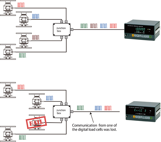
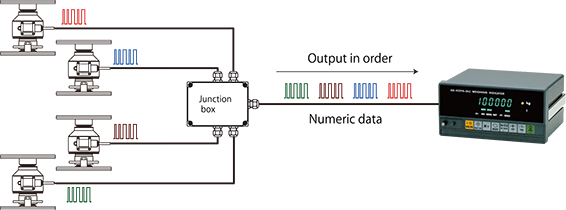
*Summing box
A summing box connects the wiring of each load cell when making a scale that connects to multiple load cells. Typically, resistance (buffering resistance) is put in so that the output of a load cell doesn’t influence the others. This resistance is inserted into the output (SIG+, SIG-) of each load cell and must have low temperature coefficient and measurement error.

*Thermocouple
A device that converts temperature difference into voltage. Generally, it is a junction of different metals.
There are various types suited for different temperature ranges and applications.

With analog load cells, it is difficult to detect that one of the cells is malfunctioning. However, this is easy with digital load cells because the signal of each cell is acquired separately.

Because each load cell outputs its own individual signal, the indicator can easily identify a malfunctioning digital load cell that is not sending a signal.

When summing a number of analog load cells to create a balance, the analog output (mV/V) and output resistance are adjusted by adjusting the resistance in the junction box. Generally, off-center placement error correction for each load cell is also performed in the junction box. With digital load cells, however, it is not necessary to adjust the output resistance and off-center placement error is digitally corrected at the indicator. This reduces calibration work and labor versus analog load cells.

Analog load cell cables cannot be used.

These cables are not designed for serial data communication standards, such as RS-485. Digital load cells use shielded twisted pair cables (duplex communication with 4 wires) for serial data communication.

With digital load cell cables, transmission moves in one direction and DC power (7V to 10V) moves in the other. As cables become longer, one must check for voltage drops in the DC power to ensure that the specified voltage is applied to the digital load cell.

Our digital load cells include measures to prevent incorrect wiring.
Furthermore, no problems occur when analog and digital load cells are mistakenly exchanged.

They are incompatible with analog load cells.

Analog load cells and indicators from different manufacturers can be freely combined. However, it is recommended that digital load cells and indicators from the same company be used.

While there are certainly many basic components in the common digital load cell specifications, companies can add their own unique specifications. Therefore, combining digital load cells and indicators from different companies may create problems and it is necessary to choose products from the same company.

Furthermore, the applied voltage of digital load cells vary by company so care must be taken when using hardware from other companies.

A digital load cell outputs digital (numerical) data to an indicator using serial communication, such as the RS-485 standard, and a Modbus-RTU communication protocol. Besides the load (measurement data), it is possible to acquire overload data of the load, the name of the manufacturer, the machine type, and the serial number as digital values, which is not possible with analog load cells.

A digital load cell outputs numbers to the indicator while an analog load cell outputs voltage.

The output of analog load cells depends on applied voltage (the voltage supplied to the load cell by the indicator). For example, if a voltage of DC 10V is applied to a load cell with a rated output (the voltage difference of the output when unloaded and the output at the rated capacity) of 2 mV/V and a load at the rated capacity (the maximum load the load cell is designed to measure while maintaining these specifications) is applied, the load cell outputs 20 mV (2 mV x 10V). If the applied voltage is DC 8V, the output is 16 mV (2 mV x 8V). On the other hand, digital load cells output the load applied to the load cell as a digital value (a number), regardless of the applied voltage.

With a typical analog voltage output load cell (hereafter referred to as an analog load cell to distinguish it from a digital load cell), analog to digital (A/D) conversion is performed at the indicator. On the other hand, digital load cells perform A/D conversion using an internal A/D converter. After arithmetic processing to correct peculiarities in the load cell output, a digital signal is sent to the digital load cell indicator.

We often get questions like, “I’ve made a scale by combining a load cell and an indicator. I have to increase the capacity of the scale and want to change the capacity setting of the indicator. If I do that, do I have to recalibrate it?” We probably get this type of question a lot because of the difficulty of placing counterweights with large silos and automatic scales.

In such cases, recalibration is probably not necessary. Increasing the capacity a few percent won’t cause many problems even if a recalibration is not performed. Since the linearity of the indicator and load cell is sufficient, changing the capacity a few percent won’t cause much error.

Furthermore, weighing indicators are calibrated using an internal resolution that is finer than the displayed resolution and this data is stored in nonvolatile memory. As a result, the zero point and span remain the same even if the minimum scale value is subsequently changed.

Nevertheless, it’s better to recalibrate when changes have been made to the scale. Furthermore, it’s important to make sure that insufficient mechanical strength or other issues do not cause problems when increasing the capacity setting.