Customers often ask me, “For the applied voltage of load cells, the higher the better, right?” These customers usually have an understanding of electricity and logically point out that, “If the applied voltage of the load cell is doubled, the output voltage doubles proportionally. This in turn will increase the signal/noise ratio and reduce the variation of the indicator value by half”.

Well, another tricky question, I always think. That’s because when I explain my answer, customers often tell me that they are confused. What the customers are saying is definitely correct in principle. However, there’s a reason why it doesn’t tell the whole story for load cells.

Let’s look at a question about Ohm’s Law.

Q: If 5 V and 10 V are applied to a resistance of 100 Ω, what are the respective power levels?
A: P (power) = V2/R

For 5 V, 5*5/100 = 0.25 W
For 10 V, 10*10/100 = 1 W

We can see that power increases in proportion to the square of the applied voltage.
In other words, doubling the applied voltage quadruples the heat generated.
That’s why all manufacturers regulate the maximum applied voltage of their load cells.
If the applied voltage exceeds this limit, combustion may occur.

Furthermore, temperature increases caused by the dissipated power create a temperature difference between the load cell and ambient air. This causes convection, which is like the steam slowly rising from a hot cup of coffee. The convection causes ripples in the surface temperature of the load cell, which causes the surface material of load cell (aluminum, steel, etc.) to expand and contract. This is detected by the strain gauge and causes the indicator value to fluctuate. What’s more, when a lot of heat is generated, even a small amount of air from outside the instrument may also cause irregularities in the surface temperature of the load cell, which may also cause the indicator value to fluctuate.

So this leads to another difficult question: “So that means the lower the applied voltage of the load cell, the better?” Actually, when the applied voltage of the load cell is small, the output power is lower, which makes the load cell more likely to be affected by disturbances such as ambient noise. This leads to the question, “So, which is it?” Even if the applied voltage is low and the noise ratio increases, it’s OK as long as you use a filter that can eliminate as much noise as possible. This means that even if the applied voltage is halved and the noise ratio is doubled, it’s better to increase the performance of the noise-eliminating filter by 2 times or more.

That’s why A&D lowered the applied voltage to 5 V for the load cells in their new weighing indicators. And lower power consumption is more environmentally friendly, right?

Since their output is so faint, load cells require adequate noise countermeasures such as quality shielded cables or protective tubing. In most cases, the strongest source of noise in the environment around load cells and weighing gauges is power frequency noise, which is generally 50 or 60 Hz. This is known as hum noise.

However, A&D’s weighing indicators have excellent noise elimination properties against this power frequency and are not very affected by it. Strangely, this can be a problem as there are even customers who do not feel the need to use shielded load cell cabling. (Of course, we do not recommend this.)

However, power frequency is not limited to 50 and 60 Hz. The closest one is an inverter. Inverters control the speed of a motor by changing the power frequency, and this generates frequencies other than 50 and 60 Hz. Furthermore, inverters generate various frequencies and voltages through on/off switching at very short intervals when switching between direct current and alternating current, and this switching frequency also generates noise. Therefore, various frequencies, along with strong noise, are often generated in environments in which inverters are used. As mentioned above, the most basic way to counter this noise is through shielded wiring and piping. However, our products that use the High Performance Digital Filter are designed to resist not only sources of vibration such as the floor but also the various frequency noises generated by inverters. We recommend these products to customers worried about noisy environments.

The fuses of devices that have been used for many years sometime suddenly blow and often metal fatigue is the cause. But why would a fuse with no moving parts be affected by metal fatigue? When the power is switched on, the inrush current instantly heats and expands the fuse. Later, the fuse returns to its original condition. This process repeats again and again, which causes wear over the years that may cause the fuse may blow.

Even with the same fuse, high ambient temperatures make a fuse more likely to blow. Higher temperatures lower the resistance value of the fuse, which makes heating and fusing more likely. Because of this characteristic, it is normal practice to select a fuse 1.5 to 3 times the rated current of the device used.

We received an inquiry from a customer about a fuse that blew after they switched from an old to a new weighing indicator. Apparently, the old one was over 20 years old. The power circuit of an indictor that old is likely to be a series type rather than the currently popular switched-mode type.

When you choose a power fuse, you first must consider the power consumption of the device being used. At minimum, you need a fuse for a current capacity that can supply the power consumed. So, how much of a margin is needed for fuses?

Let me ask a tricky question. Imagine you have a 100 V, 60 W incandescent light bulb. When you light the bulb, how much current flows? The calculation would be: 60 W ÷ 100 V = 0.6 A. So, is it OK to use a fuse with a 0.6 A rating? The answer is “No”. Let’s try and measure the resistance value of this incandescent light bulb. A 60 W light bulb that I have on hand has a resistance value of a mere 14 Ω. If 100 V is applied, the current flowing is 7 A, right? If you actually apply 100 V, a large current flows at first but it gradually drops and eventually reaches 0.6 A. Since the filament temperature is low when the power is first switched on, the resistance value also is low, but as the temperature rises, so does the resistance value. Therefore, if the characteristics of the bulb and fuse are mismatched, the fuse blows as soon as the power is switched on. This large current when the power is switched on is called inrush current.

Let’s bring the discussion back to weighing gauges. Because they are low in noise and simple, series-type power sources (power circuits using large power transformers) were used for the power circuits of electrical devices like weighing gauges until the 1980s. These power circuits were inefficient but the inrush current was not so large. However, currently popular switched-mode power supplies have a large inrush current when the power is switched on but this current tends to flow for only a short time. Therefore, changing weighing indicator types, even for one with similar power consumption, makes it likely that the fuse will blow.

So, what can we do about this problem? You must switch to a slow-blow fuse. There are three main types of fuses.
– Fast blow
– Normal blow
– Slow blow

Slow-blow fuses strongly resist the inrush current when the power is switched on and blow like a normal fuse with further overcurrent. These fuses can be identified by the letter “T” before the rated current marking. For example, a 1 A slow-blow fuse would be marked “T1A”.

For reference, the following A&D weighing gauges use switched-mode power supplies: AD-4401, AD-4402, AD-4404, AD-4408A/C, AD-4530, and AD-4532B. (as of May 2011)

We started an investigation after hearing from a customer in South East Asia. He said that weighing indicators were quickly breaking, even after several replacements, and that one had broke after 2 weeks just recently.

However, the so-called quickly broken indicator was one of our long-selling items and not easily broken. When such cases occur, the cause is often peculiar to the location. However, this site was overseas and not easy for us to visit so we asked the customer to send us a connection diagram.

I soon received an extremely hard-to-read scan of a ragged diagram that looked like it was from some ancient text. What’s more, it was in Japanese. It appeared to be for a scale that had been assembled by a Japanese company around 20 years ago and then exported overseas.

While it was very hard to make out the diagram, I found the notation “Power cord 2P” while zooming in on it. “Power cord 2P” means an AC power connection with only two pins and no ground pin. I thought, “Well, there’s your problem!”

Certainly, a weighting indicator will run without a ground pin and many consumer electronics have a power cable with only two prongs.

However, unlike consumer electronics, weighing indicators have a number of long cables, including the load cell cable, and they are sometimes connected outdoors.

As a result, if an ungrounded indicator receives noise voltage such as a lightning strike or static electricity, the voltage will pass through the electric circuits inside the weighing indicator and damage them.

While many Japanese homes have 2-pin AC outlets, offices and factories commonly have 3-pin outlets with a ground terminal. Unfortunately, most people ignore grounding because they know from experience that devices will work without it.

I urge anyone reading this article who uses a desktop computer to check that it is properly grounded.

When one of our experienced engineers was visiting a customer site, he received a complaint that, “If a new scale is made with A&D load cells and indicators, the indicator value shifts tens of digits in an hour”.
The engineer carefully inspected the location and checked everything he could think of, such as loose screws or bonding terminals, soiled PCBs, the material quality of the load cell cables and terminal blocks, and the presence of shielded wiring. Still, when it came time to leave, he still hadn’t found the cause.

However, the always careful engineer thought, “All that’s left is the summing box the customer made!” and then asked to borrow the PCB inside the summing box*.

When he got back, he showed me the board. From looking at the terminal block made from PBT resin, which has good insulation properties, and the expensive-looking, shiny-black resistor, it was impossible to see any problems anywhere.
Still, I tried putting a magnet near the lead wire of the resistor just to be sure. The magnet was forcefully pulled to the lead and stuck to it with a snap. In other words, it was highly likely that the lead wire of the resistor contained iron.

Because iron is both inexpensive and strong, it is used in many applications. However, thermoelectric force occurs easily between iron and copper, so it is not suited for circuits that handle tiny voltages.

In this case above, the lead wire of the resistor acted as a thermocouple* and converted a small temperature imbalance to a voltage, which was output to the indicator.

Later, it was confirmed that the resistor was designed for heat and impact resistance. The lead wire was a special type that used copper wire with an iron core. We solved the problem by showing the customer resistors with low thermoelectric force.
The experience made me acutely aware that even resistors cannot be treated lightly.

*Summing box
A summing box connects the wiring of each load cell when making a scale that connects to multiple load cells. Typically, resistance (buffering resistance) is put in so that the output of a load cell doesn’t influence the others. This resistance is inserted into the output (SIG+, SIG-) of each load cell and must have low temperature coefficient and measurement error.

*Thermocouple
A device that converts temperature difference into voltage. Generally, it is a junction of different metals.
There are various types suited for different temperature ranges and applications.

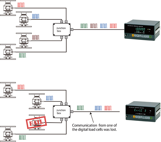
With analog load cells, it is difficult to detect that one of the cells is malfunctioning. However, this is easy with digital load cells because the signal of each cell is acquired separately.

Because each load cell outputs its own individual signal, the indicator can easily identify a malfunctioning digital load cell that is not sending a signal.

When summing a number of analog load cells to create a balance, the analog output (mV/V) and output resistance are adjusted by adjusting the resistance in the junction box. Generally, off-center placement error correction for each load cell is also performed in the junction box. With digital load cells, however, it is not necessary to adjust the output resistance and off-center placement error is digitally corrected at the indicator. This reduces calibration work and labor versus analog load cells.

Analog load cell cables cannot be used.

These cables are not designed for serial data communication standards, such as RS-485. Digital load cells use shielded twisted pair cables (duplex communication with 4 wires) for serial data communication.

With digital load cell cables, transmission moves in one direction and DC power (7V to 10V) moves in the other. As cables become longer, one must check for voltage drops in the DC power to ensure that the specified voltage is applied to the digital load cell.

Our digital load cells include measures to prevent incorrect wiring.
Furthermore, no problems occur when analog and digital load cells are mistakenly exchanged.