Posts

For this installment of the developement series I would like to share some details on the ongoing development of the successor models to the GX/GF Series of Precision Balances released 15 years ago.

These top loader balances have the mass sensor mechanisms and the circuit board housed inside a case with the weighing pan placed on top as the name suggest. The minimum weighing displays are 1mg, 10mg, and 0.1g and the weighing range is between 200 grams and a few kilograms. The ratio of the minimum display to the capacity is approximately 100,000~1,000,000 to 1. These balances are capable of high resolutions and sensitivities and as such make up a key market area for weighing instrument commodities and are used in a wide range of applications from the inspection and quality control of parts on a production line for industrial products to experiments and research at universities. Also the exceptional cost performance and user-friendliness of these balances make them ubiquitous in biological and medical research as well as food and materials development laboratories.

I have mentioned before that in the year 2000 when the original GX/GF was developed, three or four competitors had already proposed new “mono” (single unit) structure mass sensors. However, to me following this idea would only entail playing catch up to other companies. Moreover using a specialized “mono” structure would limit the processing methods, requiring capital and investment in production facilities. The large initial investment was a cause for worry that led us to conceive the super hybrid sensor (SHS) with a method of combining modular high precision parts instead of having a “mono” structure. I have written previously about the research leading up to our unique hybridization and realization of the actual sensor.

When we were developing the SHS, Japan was at a high level of technological sophistication and fortunately we had maintained long-standing cooperative relationships with manufacturers of high quality parts. They boldly set out on the machining process of the Roverbal structure, which was the key component of the SHS that we planned. This would result in the production of specialized components being done with general processing machinery turning the hybrid structure into reality. Some time has passed since the development of the original SHS and even now, the GX/GF series equipped with the first SHS remains securely as the leading balance in Japan. At the same time the SHS has evolved and is currently finding uses in devices from microbalances to industrial balances and sensors for moisture analyzers.

When the SHS was being developed, our competitors were focused on mono structure designs so proposing a hybrid structure was met with significant criticism from within A&D, with people suggesting it was a hopeless endeavor. However, to use an example from the automotive industry, most customers don’t really care whether the camshafts of a car are SOHC or DOHC, or if it is a turbocharger or supercharger, or if it’s a diesel or hybrid vehicle. What people actually care about is the comfort when driving (acceleration, stability, collision safety, space, storage, convenience) and fuel efficiency, and whether they are commensurate with the initial investment and required maintenance fees. In other words, the materials that are advertised as relevant to cars are only means, not the ends..

Even for balances, if the performance (weighing stability, response speed, usability) is good then debating the method to obtain that performance is meaningless. We developed SHS as the mass sensor that would give the GX/GF series the fastest response time in the world and make maintenance simple and cheap while reducing the cost of components.

Although the GX/GF has become the market leader in the past 15 years, we planned a complete model change and started development of a newer mass sensor to make a more user friendly product 3 years ago. This was due in part to the rapid technological improvement in electronic parts. This new model would be the last mass sensor that I personally would develop after working on 6 types since the first HX in my 27 years of employment at A&D. I have therefore planned a product that should remain at the top of its class for a decade from now and also have proposed solutions to the many performance inhibiting problems discovered with the mass sensor that led to dead ends in development. During such dead ends, engineers will be put to the test. The conventional way to continue development during these times is reshuffling people because engineers that begin to list reasons why something can’t be done cannot be persuaded to change. More than 2 years was required to get the desired performance and in that time an engineer has quit due to differences in opinions.

In our current project we ended the shaving process for corner-load adjustment while following the proposed SHS hybrid structure and adopted a structure that uses screws for corner-load adjustment. We equipped the sensor with a feature that can announce when there is an excessive load. This is to protect the mass sensor from damage for when automated production machines are used, as the load applied by automated machines can reach around 3 times greater than when the balance is loaded manually. In addition, we adopted a new leveling mechanism and function that allows measurement of flow rates of liquids. These features are a new plan focused on the place of use and have not been included in any balance up until now.

I would like to explain the technical specifications of the new additions in further detail over several installments. This time I will cover the composition of the device and the alarm for excessive loads.

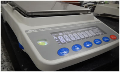
The measurement display area is larger in the new GX/GF and the display method has been changed from VFD to reverse backlit LCD. The large white characters make the display easier to read. We have also added a light to the spirit level to facilitate horizontal adjustment in darker areas.

GX-A/GF-A Series

Now, I will move on to the overload warning. Balances are calibrated with weights of known mass at the place of use/installation. The purpose of this calibration is to compensate for the acceleration due to gravity which differs depending on location. The force F = M0 × G0 where M0 is the mass of a known weight, G0 is the location’s gravitational acceleration is balanced with the electromagnetic force through the intermediary of a fulcrum. When a load is added a beam moves and its displacement is measured by a position detection unit with an infrared sensor, and the current of the electromagnetic unit is controlled so that the beam comes to the same location. If the current is controlled, the load on the pan and the Lorentz force produced from the electromagnetic unit can be put at equilibrium and an electromagnetic force proportional to the added load is produced.

We call using the electromagnetic force to balance the weight (mass) on the pan the electromagnetic equilibrium method. Currently almost all top-loader balances and analytical balances use this method. In the electromagnetic equilibrium method the mass of an unknown object is determined by balancing the force (current) produced by the electromagnetic unit with the unknown object.

With this method, the position sensor output changes proportionally with the load, and afterwards the closed controlled beam returns to its original position by the electromagnetic force. The displacement from the position sensor changes with the load. If the derivative of that displacement is taken with respect to time, the velocity of the beam can be obtained and from that another time derivative is used to find acceleration. We found that the change in the position sensor when the impact load is added shows the displacement of the beam when the impact load is transmitted and if the acceleration is obtained from the second derivative of position, the static load equivalent applied to the mass sensor by the impact load can be evaluated.

An experiment to prove our hypothesis showed that when a person places something on the balance pan with their hands there is a three-fold difference in the impact that the mass sensor receives compared to when the same mass is placed on the balance pan with a pneumatic actuator. That is, we showed that 1kg (1G) loaded by hand, registers as a load of 3kg (3G) even after adjustments by air cylinders or other devices. Giving the function to process this data to the balance itself and showing the result of that evaluation on the display unit will allow balance users to see that the weight is overloading the system.

In the past there were some instances of balances built for production lines for large automotive manufacturers becoming damaged after a certain period of time. To remedy this, A&D, the automated machine manufacturer and the end user conducted an investigation to determine the cause of this problem. The investigation found that after a short amount of time the mass sensor unit became damaged for the balances at all of the manufacturers. At this time it was speculated that if the balance could determine and transmit its condition, developers could plan against damage to the balance before it happened. We determined that by displaying the equivalent load experienced by the mass sensor to the user and issuing a warning about how the balance is used, preventative measures could be formulated to protect the balance.

The GX/GF-A is the first in the weighing industry capable of evaluating impact loads and I believe it will find many applications on the production line as a versatile weighing instrument due to its quick response speed and stability.

Analytical balances are very sensitive. Therefore, they are heavily affected by the environment in which they are installed and the way measuring personnel handle them. With regards to methods for assessing the environment, running AND-MEET (*1) will yield a judgment and assessment, and from there a concrete process for improving the environment can be proposed. In addition, in “Development Story 17”, I explained a method for selecting a location for measuring instruments. So, for this edition of “Development Story”, I will discuss proper handling with a focus on analytical balances.

The basic motto for weighing instrument operation is “quick and accurate”. So in the case of someone taking time to slowly open and close a breeze break door, these words would tell us that such is not an optimal way of conducting measurement. It means that by increasing the time that the breeze break door is open, the air within the breeze break changes, and the weighing area’s temperature will change. From amongst the analytical balances, I will use the microbalance, capable of measuring 1 millionth of a 1 yen coin (1 gram), as an example.

For instance, in bioscience research fields, many labs use micropipettes. Even with pipettes, we know that without accurate and experienced handling, random errors occur, and if there is a problem with the pipette itself then systematic errors can occur. The minimum capacity for a micropipette is around 1 to 2 μL. 1 μL is an extremely small amount compared to what we are used to in our daily lives. However, if 1 μL of water is converted into mass, it becomes 1 mg, and a sensitivity of 1 mg is a minimum display for general-purpose precision balances in the weighing instrument industry. Yet microbalances can measure 1/1000 of this unit – an ability to measure where 1 digit = 1 μg is stipulated. In other words, determining 1 μg is more difficult than using micropipettes, so it can be said that it’s clear that experience and accuracy are demanded in measurement operation.

Electronic balances deliver weighing results via digital display: from general-purpose balances with a minimum display of 10mg or 1mg to analytical balances with minimum displays of 0.1/0.01/0.001mg. Because of this, people think that if the weighing sample is simply placed on the pan, an accurate weighing result will be displayed instantly. However, with readability that is orders of magnitude more precise than the minimum capacities of micropipettes, one must question whether the result displayed is really correct, and recognize that instability in the displayed result can be quite natural depending on how the instrument is operated.

Therefore, I will explain how errors in weighing occurred using actual examples from weighing sites.

1) Effects of static electricity

For weighing instruments used in production lines using automated machines or at sites conducting plastic injection molding, there have been instances of displays becoming unstable, or measurements changing in one direction with the passage of time. This phenomenon is called “drift” in the weighing industry. Currently, in the production processes for pharmaceutical manufacturing, primary and secondary batteries, electronic parts such as IC chips and LEDs, and resin molds, many weighing instruments are used for quality control. But on these production lines, the environment is usually like that of a clean room, and we have confirmed many areas with 24-hour air conditioning and humidity levels sometimes below 20% due to the undesirability of moisture. In other words, it is dry, and friction from insulated material caused by the moving around of objects causes static electricity to build up easily. Moreover, people working on the line or research can sometimes build up around 10,000 volts of electricity themselves. Under these circumstances, the effects of static electricity become greater, and errors of a few dozen milligrams can easily occur. (*2)

If the humidity in the weighing instrument’s installation environment cannot be increased over 40% or if electrical build up occurs faster than electrical discharge, please introduce a static eliminator and conduct weighing operations after actively removing charges from the weighing sample.

2) Effects of temperature

Let’s say you check the quality of a molded item right after resin molding it by measuring it on a weighing instrument, or you measure out some pharmaceuticals into a handheld vial and then weigh it, or you take a sample from another location and bring it in to measure it right away. In scenarios like these, a difference between the weighing sample’s temperature and the weighing area’s temperature will occur. This temperature difference will become a weighing error. The reason for this is that when the sample’s temperature is higher than the room temperature, a layer of warmer air is created around the sample, and a slight upward air current is created. That air current has the effect of pushing the weighing sample up, and the weighing measurement will come up light at first. When the sample later reaches room temperature, the original weight will be displayed.

It depends on the temperature difference and the shape/material of the sample, but weighing errors on the order of a few dozen milligrams can occur.

thermograph image
Fig.1 Thermograph image of a container after being gripped by hand

Fig.1 shows the results of thermograph observations of a coffee can placed on an analytical balance. The can has been gripped for a few dozen seconds before being placed on the pan. Metal is especially conductive of heat, and a deviation from ambient temperature of a few °C can occur in a short period of time. It is known that the convection current generated by this temperature difference will affect weight measurements. (*3)

I experienced this personally more than 10 years ago, when we were setting up mass production of weights with tolerances conforming to the OIML Class E2 standard and compositions conforming to the Class F1 standard. In this instance, we found that our weight-adjusted 200 g weight had grown heavier on a 0.1 mg level the next day. We had touched the weight with gloves, but after conducting weight adjustment and screw tightening, we found that our body heat had warmed up the weight slightly. It was a good experience for me to understand why people say it is not good to touch weights directly with one’s hand. In places where weighing instruments are being used, one may see people picking up weights with gloves and calibrating, but at least when it comes to analytical balances, we recommend doing calibration and performance checks using tools such as tweezers.

3) Effects from work in the weighing area

Analytical balances come standard with a breeze break. It’s there to stop drafts and maintain stability within the weighing area. However, if the breeze break’s door is operated roughly, an impact will occur at the end of the swing and the force will reach the balance’s weight sensor. This can result in variations in the zero point, and risks reductions in repeatability. But if the door is operated too slowly, the time when the door is opening and closing lengthens, and the air within the weighing area will be replaced. As a result, the temperature can become unstable and become another factor in the reduction of repeatability.

People’s hands exceed room temperature, and placing one’s hands in the weighing area can cause a disturbance in temperature. For this reason, the door should not be opened longer than necessary, the door should be operated accurately within a short period of time, and long tweezers need to be employed to avoid placing one’s hands in the weighing area as much as possible.

As an aside, I’ve searched far and wide for an off-the-shelf set of long tweezers that are usable for calibrating weighing instruments. However, I was unable to find anything fitting the description. It was then that I independently drew up plans for an ideal set of tweezers, and gave the manufacturing contract to a manufacturer near Tsubamesanjo in Niigata Prefecture. In the production of these AD-1689 tweezers, special regional production techniques that made Japan the #1 producer of eating utensils such as spoons and forks have been used. The original “monotsukuri” (craftsmanship, artisanry) techniques found throughout Japan contain skills passed down by craftsmen for more than 150 years, and it is thought that these techniques have supported Japan’s economic growth from the Meiji Restoration to the present day. I believe that continuing to support these techniques is absolutely essential to maintaining the Japanese economy going forward.

  • But I digress. I’ve summarized weighing instrument operation methods in a simple form below.
  •  When conducting weighing using a balance, special care must be taken with regards to the weighing sample’s static charge and temperature.
  •  It is especially necessary to actively introduce a static eliminator to take care of static electricity trouble in dry environments with humidity of less than 40%.
  •  For the weighing sample as well, care in controlling the temperature is needed, including measures such as not touching the sample directly with one’s hand. It is important to place the weighing sample in the weighing area beforehand, and allow it to adjust to the temperature there before commencing weighing.
  •  Weight measurement should be conducted quickly and accurately, the weighing area door should be opened as little as possible, and one’s hand should not be inserted into the weighing area.

Reading the precautions above, one may feel heavy with the difficulty of operating an analytical balance. However, please rest at ease. Lately, multiple analytical balances with internal static eliminators are on the market. Additionally, there are models which feature a weighing preparation room where the weighing sample can be placed to allow it to adjust to the temperature. And there is also the set of long tweezers for weighing operations which I wrote about.

Regarding precautions aside from weighing operations, it is necessary to connect the balance to a power source the day before weighing to ensure that it is stable. In the case of weighing instruments at the semi-micro level and below, it can take from 6-8 hours for a connected machine to completely adjust to the room temperature. Additionally, one must do as much as they can to ensure that vibrations, pressure changes, temperature changes and humidity changes do not occur in the weighing room. As part of this, foot traffic in and out of the room should be reduced as much as possible.

Lastly, regarding handling of weighing instruments, the characteristics of electronic components of electronic balances become more stable the longer the instrument is hooked up to a power source. The thermal distribution within the device, including the weighing chamber, will become even. Since these instruments do not use much electricity, I recommend continuous connection to a power source if possible.

I believe that going forward, weighing instrument manufacturers shouldn’t just conduct development that’s all about how good the performance is or how many features there are, but that they should also come up with solutions which are easier to use on-site and which also include peripherals to display and reduce weighing errors. Moreover, this proposal means providing a comprehensive weighing and measuring service with everything from analysis to assessment, using environmental measurement, communication utilities, data management, graphing functions, and more. What is important to manufacturers at such a time is knowing the weighing and measurement market that forms the actual usage locations for these instruments. I would like to continue emphasizing market surveys and providing original products according to principles emphasizing the best results for all parties involved.

*1 Regarding AND-MEET: Please refer to the 28th Sensing Forum: Investigation of the Basic Performance of Analytical Balances (PDF 1.28MB)
*2 Regarding the effects of static electricity: Please refer to Training Material for Balances (1) (PDF 437KB)
*3 Regarding the effects of temperature on weighing samples: Please refer to Training Material for Balances (1) (PDF 437KB)

In this edition, I want to talk about the installation environment for analytical balances, which have seen a lot of trouble on the market. In the next edition, I’ll be talking about how to properly use an installed analytical balance and take measurements accurately, using knowledge gained from actual usage scenarios.

Because analytical balances are very sensitive, the environment in which they are installed will affect them a great deal. For the same reason, we know that the way in which operators handle the balances also has a large effect. As far as assessing the measuring environment is concerned, thanks to our measurement environment evaluation tool option “AND-MEET” (*1) and our market response, it’s possible to get a clear idea of how to improve the measuring environment from a balance installation environment assessment. So for this edition, I’ve put together some general information about installation environments.

Since the March 11 Disaster, we continue to have frequent earthquakes in eastern Japan. This is a special concern for analytical balances capable of measuring on a microgram level, for not only do they pick up earthquakes, but also things such as movement of people, handcarts, and forklifts, as well as vibrations and changes in room air pressure from the opening and closing of doors.

As for weather effects, the force of wind from passing low pressure systems like monsoons and typhoons can cause problems due to buildings shaking, which becomes an even greater issue on higher floors. Buildings built with a quake-absorbing structure, which have become more common recently, are designed with shaking as a given. Such structures can shake for days due to wind pressure or earthquakes.

For situations like these, we have confirmed that passive anti-vibration tables such as the AD-1671 improve issues with repeatability. On the other hand, we have found that despite their high cost, active air suspension anti-vibration tables used for optical measuring instruments actually become a source of vibration, and negatively affect analytical balances.

Administrators of balances often ask us about the permitted specifications of an installation environment for an analytical balance. A&D recommends the following: (1) daily fluctuation of temperature of 4°C or less (within 10 – 30°C) and short term fluctuations of 0.2°C/30 minutes or less, (2) daily fluctuation of humidity of 10% or less, and (3) daily fluctuation of air pressure of 10 hPa or less. In particular, regarding the short term temperature fluctuations written about in (1), it is known that the repeated slight changes in temperature caused by air conditioning have an especially destabilizing effect on balances’ zero-point display. To cite an extreme example, our data shows that even within the sort of windy environmental setup specified by the Ministry of the Environment’s Manual for Continuous Monitoring of Air Pollution (a.k.a. PM2.5), using the AD-1672 tabletop breeze break (which surrounds the balance area) can have such an improving effect that catalog specifications for the microbalance can be met. (*2)

Allow me to explain proper installation of a balance using an actual example. Fig. 1 is a rough sketch using the seminar room in our R&D center’s 2nd floor as a model. The seminar room is about 10 meters long on each side, and there are multiple air conditioning units in the central area of the ceiling. It would be rather large for a lab, but it resembles many labs in terms of the layout of things such as the air conditioners and lab tables. I’ve numbered the tables in this diagram from #1 – #16. I would like you as well to think about which spot is the best place in the seminar room (lab) to install a balance.

laboratory layout
Fig. 1 – Diagram for evaluating balance placement

To select a location for the balance, first we must find a location that minimizes temperature fluctuations, which have the greatest effect on balances’ performance. To be more precise, a place that is (1) out of direct sunlight and (2) far away from air conditioner vents. Next, we select a (3) corner of the room next to the wall. The center of a room has weaker construction, and the floor tends to shake more easily. However, there tend to be structural supports in the corners of a room, and they tend not to shake easily. In addition, even if room temperature is being controlled at a certain level, floors and walls often go below room temperature, especially during winter. Level temperature means that the temperature is evenly distributed (the flow of heat is even), but in the case of walls which have outside air on the other side, balances near that wall may be constantly subjected to outside temperature variations. For the same reason, installation should not be done near window glass. That is why it is best to (4) install the balance near a wall which has another room on its opposite side. As for the table on which it is installed, (5) a hard balance table with high heat capacity should be used, and (6) the balance table should be separated by a few centimeters from the wall and other tables in order to isolate it from heat and vibration coming from the wall and floor. A (7) dead end area with low foot traffic should be selected because people tend to come and go through the central part of a room. To further reduce people’s influence, (8) an area far away from the door should be used, on a table where (9) only measurement is conducted in order to prevent vibration from people’s actions from affecting the balance. Additional preconditions are that the room and wall where the balance is located should be (10) far away from routes with high traffic or heavy objects moving, and (11) on as low a floor as possible.

Using the above conditions, we can determine that within Fig. 1, the best areas in the room to place a balance are #3 as well as #2, the areas where the effects of direct sunlight are low, air conditioner vents and windows are far away, routes where people move and doorways are far away, and near an area where structural materials such as supports are installed. Issues with #3 include being near a wall to the outside, and near a wall to a hallway, but I believe that will not be an issue because only people pass through the hallway.

The above constitutes a general assessment of balance installation environments, but labs often have individual circumstances, such as having a heat-treating furnace, or there being a lot of people coming and going during the day, and so on and so forth. Ultimately, running AND-MEET in the locations where balances are to be placed, assessing the environment there, making any problems clear and developing concrete measures to deal with them is thought to be the best course of action.

To sum up the above, here is what is required of a balance installation environment.

  • Be especially sure to consider the room temperature stability, and do not place a balance near an air conditioner vent in order to reduce the effects of temperature variations. If there is no other option, then utilize things such as tabletop breeze breaks or partitions to cut off direct wind.
  •  The balance should be placed in an area out of direct sunlight, away from routes people use and away from persons working on other things. To minimize the effects of vibrations, the central area of a wide floor should be avoided, and an area near the building’s supports should be selected. At this point, the balance table should be separated a few centimeters from walls and supports in order to isolate it from vibrations and heat from the building.
  •  To reduce effects from vibrations, the balance should be placed in a location as far as possible from paths for moving heavy objects.
  •  The building will shake when low pressure systems cross the area, so install the balance on as low of a floor as possible. In addition, to reduce the effects of the building shaking due to earthquakes and vibrations, an anti-vibration table should be installed.

40 years have passed since the balance was transformed into an electronic device using microcomputers. Since then, digitalization has progressed, and the balance has come to be regarded as an instrument which can be easily used by anyone. However, at present, analytical balances have a resolution of 1/20,000,000 or more, and a certain level of skill and preparation is required to enact exact measurements. In particular, with regards to balance installation, there are many matters to be taken into consideration. I hope this article will help you understand the best environment, install the machine and set up the environment, and allow you to conduct reliable measuring work.

*1 Please refer to Development Story 12: Solutions Provided by the BM Series Part II
*2 Please refer to the 28th Sensing Forum: Investigation of the Basic Performance of Analytical Balances (PDF 1.28MB)