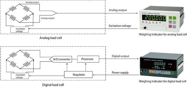
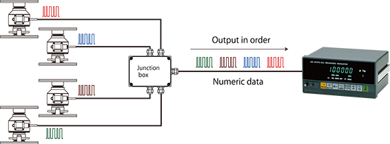
A digital load cell outputs digital (numerical) data to an indicator using serial communication, such as the RS-485 standard, and a Modbus-RTU communication protocol. Besides the load (measurement data), it is possible to acquire overload data of the load, the name of the manufacturer, the machine type, and the serial number as digital values, which is not possible with analog load cells.

A digital load cell outputs numbers to the indicator while an analog load cell outputs voltage.

The output of analog load cells depends on applied voltage (the voltage supplied to the load cell by the indicator). For example, if a voltage of DC 10V is applied to a load cell with a rated output (the voltage difference of the output when unloaded and the output at the rated capacity) of 2 mV/V and a load at the rated capacity (the maximum load the load cell is designed to measure while maintaining these specifications) is applied, the load cell outputs 20 mV (2 mV x 10V). If the applied voltage is DC 8V, the output is 16 mV (2 mV x 8V). On the other hand, digital load cells output the load applied to the load cell as a digital value (a number), regardless of the applied voltage.

With a typical analog voltage output load cell (hereafter referred to as an analog load cell to distinguish it from a digital load cell), analog to digital (A/D) conversion is performed at the indicator. On the other hand, digital load cells perform A/D conversion using an internal A/D converter. After arithmetic processing to correct peculiarities in the load cell output, a digital signal is sent to the digital load cell indicator.

We often get questions like, “I’ve made a scale by combining a load cell and an indicator. I have to increase the capacity of the scale and want to change the capacity setting of the indicator. If I do that, do I have to recalibrate it?” We probably get this type of question a lot because of the difficulty of placing counterweights with large silos and automatic scales.

In such cases, recalibration is probably not necessary. Increasing the capacity a few percent won’t cause many problems even if a recalibration is not performed. Since the linearity of the indicator and load cell is sufficient, changing the capacity a few percent won’t cause much error.

Furthermore, weighing indicators are calibrated using an internal resolution that is finer than the displayed resolution and this data is stored in nonvolatile memory. As a result, the zero point and span remain the same even if the minimum scale value is subsequently changed.

Nevertheless, it’s better to recalibrate when changes have been made to the scale. Furthermore, it’s important to make sure that insufficient mechanical strength or other issues do not cause problems when increasing the capacity setting.

One day, a customer called and said, “I’ve bought a lot of A&D load cells and the indicator value varies just by touching the load cell cable on several of them”. We carefully inspect the operation of our load cells before we ship them so we doubted that there could be that many defective items in one place.

We asked the customer how the indicators were being used. Even after extensive questioning, we couldn’t determine the cause of the problem so we asked one of our service engineers to go and check things out.

The service engineer reported that, “The indicator value definitely changes just by touching the cable. What’s surprising is that it doesn’t seem to happen when you touch far away from the terminal”.
“When the load cell is connected to the terminal directly without using a crimp-on terminal, it’s fine,” he continued. “It’s weird. The crimp-on terminal shouldn’t affect the indicator value…”
After a little more investigation, we finally found out what the problem was. The crimp-on terminals being used didn’t match the thickness of the conductor of the load cell cables. That’s why touching the cable changed the contact resistance and negatively affected the indicator value. If the contact resistance of the EXC terminal applying power to the load cell increases, the sensitivity of the load cell drops similarly.
The input resistance of many load cells is 350Ω. Even if the contact resistance increases by a mere 35 mΩ- or 1/10,000th – the load cell output drops by 1/10,000th. This shows why it’s dangerous to use ill-fitting crimp-on terminals like this.

When troubleshooting in the field, it’s important to get the correct information right from the start. However, the cable size of the crimp-on terminal wasn’t one of the first things to come to mind and we wasted a lot of time solving this problem.

Crimp-on terminals can be convenient for making stable connections. However, if they are used incorrectly, things such as the oxidation of metal surfaces can cause unexpected problems, even after years of trouble-free use.

There are many types of crimp-on terminals with different shapes and hole diameters to suit connection cables. Be sure to choose crimp-on terminals that are suitable for your cables and use appropriate crimping tools.

After wiring a load cell, have you ever wanted to check that the connections are correct?

You can easily check load cell wiring with a digital multimeter. The following diagram shows where to measure when a single load cell is connected to an indicator. When a summing box is used to connect multiple load cells, similar measurements can be made using the terminal blocks inside the summing box.

Measurement Locations to Check Load Cell Connections

Measurements to Check Load Cell Connections

Measurement locationMeasurementNotes
EXC+SEN+Voltage drop of load cell EXC+While usually 100 mV or less, this value may exceed 1 V when extremely long load cell cables are used.
The value is 0 V for four-wire cables, since they have no SEN+ wires.
EXC+EXC-Excitation voltage for load cellThe result depends on the type of weighing indicator but 5 V and 10 V models are most common.
Check the excitation voltage specification of the indicator.
SEN-EXC-Voltage drop of load cell EXC-This value is the same as for EXC+ and SEN+ above.
SIG-EXC-Median voltage of the load cellApproximately half the excitation voltage.
SIG+SIG-Output voltage of load cellCompare with theoretical values obtained from the rated output, actual load, and excitation voltage of the load cell.If the excitation voltage is 5 V, this value is 0 to 15 mV.
If the excitation voltage is 10 V, this value is usually in the range of 0 to 30 mV.

In previous sections, it was stated that load cells benefit from the use of six-wire cables because these cables have sensors that react to the effects of changes in excitation voltage. However, the cable from the load cell is a four-wire cable. Why is this? Temperature alters the resistance of cable from the load cell. If the temperature rises, the voltage applied to the load cell drops and so does the output voltage. So, how is this problem solved? The load cell compensates for temperature changes internally and this includes changes in cable resistance. In other words, the cable from the load cell is part of the load cell. That is why a cable from the load cell must never cut. If the cable is too long, bundle it near the load cell.

As the previous section showed, achieving the best performance from load cells requires attention to connectors. This is particularly true with connectors made of nylon (listed as polyamide, PA66, etc.). Nylon is frequently used in low cost connectors because it is cheap and flexible. However, nylon easily absorbs moisture so humidity can easily lower the insulation resistance. Special attention is required when nylon connectors are used in humid environments and areas where condensation can occur. A fall in the insulation resistance of connectors may cause drift* in the indicator values. If unexplained drift occurs, consider the resistance of the connector.

A&D’s connector-type weighing indicators are equipped with high quality metal connectors as standard. *Drift: A condition in which the indicator value does not stabilize and gradually shifts or changes sporadically.

As was mentioned above, electrical noise must be eliminated to achieve the best load cell performance. How are connectors related? The contact resistance of connectors is usually several tens of mΩ. On top of this, the effects of temperature changes and deterioration are large. Load cells output minute analog signals of several μV. Therefore, errors caused by connectors have a large impact on its signal measurements. Naturally, the remote sensing function (of six-wire cables) is effective in this situation as well. The remote sensing function corrects changes in excitation voltage and eliminates most of the negative effects. In fact, even small connectors that can accommodate six-wire cable are more effective in correcting errors than large connectors with low contact resistance.

Load cells are sensors that output extremely low levels of voltage. When converted to a weighing indicator value, the gradations are often 0.5 μV or less. (This tiny voltage is equivalent to about 1/3,000,000th of that of a battery.) Furthermore, output voltage of the load cell is proportional to excitation voltage. While load cell wiring and connections may appear unusually difficult at first glance, errors can be greatly reduced by observing a few important points. Point 1: Use six-wire cable As was stated above, it is best to use six-wire cable, as the remote sensing function corrects errors due to conductor resistance and other causes. Point 2: Use the shield wire and ground properly(Ground on the weighing indicator side) A shield wire protects the minute output signal of the load cell from surrounding electrical noise. Point 3: Use well-insulated cables and terminals Well-insulated cables and terminals prevent negative effects on the minute output signal. Insulated cables and terminals allow you to maximize the potential of the load cell. We recommend proper load cell wiring for accurate measurement.

The above shows the wiring relations of the cable attached to the load cell and the six-wire shielded load cell cable. Junction boxes and summing boxes are used to actually connect them. A&D’s junction boxes, summing boxes, and weighing indicators with terminal connections have well-insulated terminals. The optional six-wire shielded cable is also well insulated.