
Checking Load Cell Connections
After wiring a load cell, have you ever wanted to check that the connections are correct?
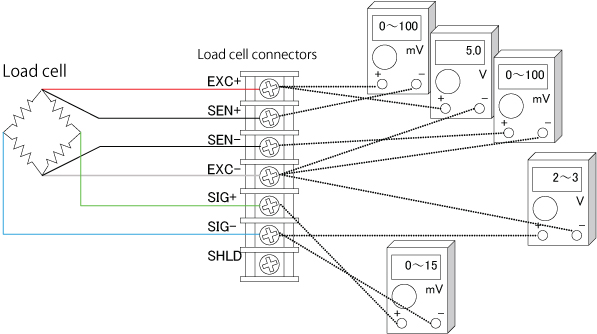
You can easily check load cell wiring with a digital multimeter. The following diagram shows where to measure when a single load cell is connected to an indicator. When a summing box is used to connect multiple load cells, similar measurements can be made using the terminal blocks inside the summing box.
Measurements to Check Load Cell Connections
| Measurement location | Measurement | Notes | |
| EXC+ | SEN+ | Voltage drop of load cell EXC+ | While usually 100 mV or less, this value may exceed 1 V when extremely long load cell cables are used. The value is 0 V for four-wire cables, since they have no SEN+ wires. |
| EXC+ | EXC- | Excitation voltage for load cell | The result depends on the type of weighing indicator but 5 V and 10 V models are most common. Check the excitation voltage specification of the indicator. |
| SEN- | EXC- | Voltage drop of load cell EXC- | This value is the same as for EXC+ and SEN+ above. |
| SIG- | EXC- | Median voltage of the load cell | Approximately half the excitation voltage. |
| SIG+ | SIG- | Output voltage of load cell | Compare with theoretical values obtained from the rated output, actual load, and excitation voltage of the load cell.If the excitation voltage is 5 V, this value is 0 to 15 mV. If the excitation voltage is 10 V, this value is usually in the range of 0 to 30 mV. |


