One day, a customer called and said, “I’ve bought a lot of A&D load cells and the indicator value varies just by touching the load cell cable on several of them”. We carefully inspect the operation of our load cells before we ship them so we doubted that there could be that many defective items in one place.

We asked the customer how the indicators were being used. Even after extensive questioning, we couldn’t determine the cause of the problem so we asked one of our service engineers to go and check things out.

The service engineer reported that, “The indicator value definitely changes just by touching the cable. What’s surprising is that it doesn’t seem to happen when you touch far away from the terminal”.
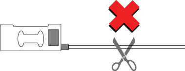
“When the load cell is connected to the terminal directly without using a crimp-on terminal, it’s fine,” he continued. “It’s weird. The crimp-on terminal shouldn’t affect the indicator value…”
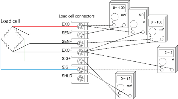
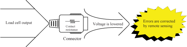
After a little more investigation, we finally found out what the problem was. The crimp-on terminals being used didn’t match the thickness of the conductor of the load cell cables. That’s why touching the cable changed the contact resistance and negatively affected the indicator value. If the contact resistance of the EXC terminal applying power to the load cell increases, the sensitivity of the load cell drops similarly.
The input resistance of many load cells is 350Ω. Even if the contact resistance increases by a mere 35 mΩ- or 1/10,000th – the load cell output drops by 1/10,000th. This shows why it’s dangerous to use ill-fitting crimp-on terminals like this.

When troubleshooting in the field, it’s important to get the correct information right from the start. However, the cable size of the crimp-on terminal wasn’t one of the first things to come to mind and we wasted a lot of time solving this problem.

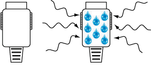
Crimp-on terminals can be convenient for making stable connections. However, if they are used incorrectly, things such as the oxidation of metal surfaces can cause unexpected problems, even after years of trouble-free use.

There are many types of crimp-on terminals with different shapes and hole diameters to suit connection cables. Be sure to choose crimp-on terminals that are suitable for your cables and use appropriate crimping tools.

After wiring a load cell, have you ever wanted to check that the connections are correct?

You can easily check load cell wiring with a digital multimeter. The following diagram shows where to measure when a single load cell is connected to an indicator. When a summing box is used to connect multiple load cells, similar measurements can be made using the terminal blocks inside the summing box.

Measurement Locations to Check Load Cell Connections

Measurements to Check Load Cell Connections

Measurement locationMeasurementNotes
EXC+SEN+Voltage drop of load cell EXC+While usually 100 mV or less, this value may exceed 1 V when extremely long load cell cables are used.
The value is 0 V for four-wire cables, since they have no SEN+ wires.
EXC+EXC-Excitation voltage for load cellThe result depends on the type of weighing indicator but 5 V and 10 V models are most common.
Check the excitation voltage specification of the indicator.
SEN-EXC-Voltage drop of load cell EXC-This value is the same as for EXC+ and SEN+ above.
SIG-EXC-Median voltage of the load cellApproximately half the excitation voltage.
SIG+SIG-Output voltage of load cellCompare with theoretical values obtained from the rated output, actual load, and excitation voltage of the load cell.If the excitation voltage is 5 V, this value is 0 to 15 mV.
If the excitation voltage is 10 V, this value is usually in the range of 0 to 30 mV.

In previous sections, it was stated that load cells benefit from the use of six-wire cables because these cables have sensors that react to the effects of changes in excitation voltage. However, the cable from the load cell is a four-wire cable. Why is this? Temperature alters the resistance of cable from the load cell. If the temperature rises, the voltage applied to the load cell drops and so does the output voltage. So, how is this problem solved? The load cell compensates for temperature changes internally and this includes changes in cable resistance. In other words, the cable from the load cell is part of the load cell. That is why a cable from the load cell must never cut. If the cable is too long, bundle it near the load cell.

As the previous section showed, achieving the best performance from load cells requires attention to connectors. This is particularly true with connectors made of nylon (listed as polyamide, PA66, etc.). Nylon is frequently used in low cost connectors because it is cheap and flexible. However, nylon easily absorbs moisture so humidity can easily lower the insulation resistance. Special attention is required when nylon connectors are used in humid environments and areas where condensation can occur. A fall in the insulation resistance of connectors may cause drift* in the indicator values. If unexplained drift occurs, consider the resistance of the connector.

A&D’s connector-type weighing indicators are equipped with high quality metal connectors as standard. *Drift: A condition in which the indicator value does not stabilize and gradually shifts or changes sporadically.

As was mentioned above, electrical noise must be eliminated to achieve the best load cell performance. How are connectors related? The contact resistance of connectors is usually several tens of mΩ. On top of this, the effects of temperature changes and deterioration are large. Load cells output minute analog signals of several μV. Therefore, errors caused by connectors have a large impact on its signal measurements. Naturally, the remote sensing function (of six-wire cables) is effective in this situation as well. The remote sensing function corrects changes in excitation voltage and eliminates most of the negative effects. In fact, even small connectors that can accommodate six-wire cable are more effective in correcting errors than large connectors with low contact resistance.

Load cells are sensors that output extremely low levels of voltage. When converted to a weighing indicator value, the gradations are often 0.5 μV or less. (This tiny voltage is equivalent to about 1/3,000,000th of that of a battery.) Furthermore, output voltage of the load cell is proportional to excitation voltage. While load cell wiring and connections may appear unusually difficult at first glance, errors can be greatly reduced by observing a few important points. Point 1: Use six-wire cable As was stated above, it is best to use six-wire cable, as the remote sensing function corrects errors due to conductor resistance and other causes. Point 2: Use the shield wire and ground properly(Ground on the weighing indicator side) A shield wire protects the minute output signal of the load cell from surrounding electrical noise. Point 3: Use well-insulated cables and terminals Well-insulated cables and terminals prevent negative effects on the minute output signal. Insulated cables and terminals allow you to maximize the potential of the load cell. We recommend proper load cell wiring for accurate measurement.

The above shows the wiring relations of the cable attached to the load cell and the six-wire shielded load cell cable. Junction boxes and summing boxes are used to actually connect them. A&D’s junction boxes, summing boxes, and weighing indicators with terminal connections have well-insulated terminals. The optional six-wire shielded cable is also well insulated.

To determine the maximum cable length, the following values are necessary: the cross-sectional area of cable conductor, the electrical resistance between input terminals of the load cell, and the number of load cells. When using A&D’s weighing indicators, the allowable two-way resistance for cables is about 10% of the resistance between the input terminals of the load cell. Therefore, the one-way resistance is about 5%. The resistance of copper wires with a cross sectional area of 1 mm2 is calculated as 0.02 Ω/m. The formula when using one load cell is as follows: The maximum cable length = the allowable cable resistance ÷ the cable resistance per meter. When two or more load cells are used, the formula is as follows: The maximum cable length = the allowable cable resistance ÷ the cable resistance per meter ÷ the number of load cells.

As an example, let’s calculate the maximum cable length when using three A&D LCC11 load cells with KO162 load cell cables.
The resistance between the input terminals of the LCC11 is 800 Ω.
The allowable cable resistance is 5%. KO162 load cell cables have a cross-sectional area of 0.5 mm2 so the resistance is 0.04 Ω/m.
The maximum cable length = 800 x 0.05 ÷ 0.04 ÷ 3
In this case, the maximum cable length is 333 m.
While the calculated length is 333 m, it may not be possible to use a 333 m cable in some environments (such as areas with a large amount of noise).

The following charts show the relation between the thickness and allowable length of load cell cables.

How do people choose load cells cables? If you look around at customers’ factories, you frequently find cables that are thicker than necessary, probably because they are worried about the resistance of the load cell cable causing measurement errors. In the 1970s, it was common practice to choose a cable that was thick as possible to reduce the negative effects of conductor resistance and temperature changes. All of our current weighing indicators have a remote sensing function that eliminates the need for thick cables. Remote sensing monitors changes in the excitation voltage* of the load cell. During A/D conversion, these changes are corrected to offset errors. The cables have six wires, two of which monitor the excitation voltage. Thinning load cell cables cuts costs and we recommend using cables with the optimal thickness to reduce installation costs.

*Excitation voltage: The application of voltage to an electric circuit from another circuit. Here, it indicates the supply of electrical power to the load cell from the weight indicator.

*How to choose the maximum cable length when using remote sensing with A&D’s weighing indicators

The common procedure is as follows:

Below is an example of how to connect an indicator and a load cell.

Suppose we prepared a load cell whose capacity is larger than 3.6kg to measure 3kg. We would like to display the results using an indicator, but what kind of indicator should we use? The specifications of the load cell and the indicator are as follows:

Let’s presume that the load cell will output approx. 12mV when 3kg is loaded,

Suppose the indicator displays the weight in units of 0.1g between 0 and 3kg. This 0.1g is called the minimum scale division. As 3kg is divided by 30000 divisions (0.1g), the resolution is said to be 1/30000. Per 0.1g, the output will be:

The input sensitivity of the indicator is 0.33μV.As this value is smaller than 0.4μV, we can use this indicator. If the input sensitivity is larger than 0.4μV, the indicator cannot display the weight in units of 0.1g.