Posts

They are incompatible with analog load cells.

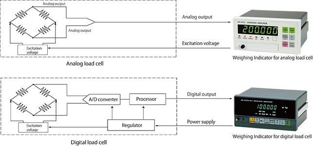
Analog load cells and indicators from different manufacturers can be freely combined. However, it is recommended that digital load cells and indicators from the same company be used.

While there are certainly many basic components in the common digital load cell specifications, companies can add their own unique specifications. Therefore, combining digital load cells and indicators from different companies may create problems and it is necessary to choose products from the same company.

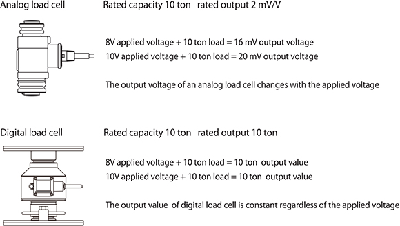
Furthermore, the applied voltage of digital load cells vary by company so care must be taken when using hardware from other companies.

A digital load cell outputs digital (numerical) data to an indicator using serial communication, such as the RS-485 standard, and a Modbus-RTU communication protocol. Besides the load (measurement data), it is possible to acquire overload data of the load, the name of the manufacturer, the machine type, and the serial number as digital values, which is not possible with analog load cells.

A digital load cell outputs numbers to the indicator while an analog load cell outputs voltage.

The output of analog load cells depends on applied voltage (the voltage supplied to the load cell by the indicator). For example, if a voltage of DC 10V is applied to a load cell with a rated output (the voltage difference of the output when unloaded and the output at the rated capacity) of 2 mV/V and a load at the rated capacity (the maximum load the load cell is designed to measure while maintaining these specifications) is applied, the load cell outputs 20 mV (2 mV x 10V). If the applied voltage is DC 8V, the output is 16 mV (2 mV x 8V). On the other hand, digital load cells output the load applied to the load cell as a digital value (a number), regardless of the applied voltage.

With a typical analog voltage output load cell (hereafter referred to as an analog load cell to distinguish it from a digital load cell), analog to digital (A/D) conversion is performed at the indicator. On the other hand, digital load cells perform A/D conversion using an internal A/D converter. After arithmetic processing to correct peculiarities in the load cell output, a digital signal is sent to the digital load cell indicator.

We often get questions like, “I’ve made a scale by combining a load cell and an indicator. I have to increase the capacity of the scale and want to change the capacity setting of the indicator. If I do that, do I have to recalibrate it?” We probably get this type of question a lot because of the difficulty of placing counterweights with large silos and automatic scales.

In such cases, recalibration is probably not necessary. Increasing the capacity a few percent won’t cause many problems even if a recalibration is not performed. Since the linearity of the indicator and load cell is sufficient, changing the capacity a few percent won’t cause much error.

Furthermore, weighing indicators are calibrated using an internal resolution that is finer than the displayed resolution and this data is stored in nonvolatile memory. As a result, the zero point and span remain the same even if the minimum scale value is subsequently changed.

Nevertheless, it’s better to recalibrate when changes have been made to the scale. Furthermore, it’s important to make sure that insufficient mechanical strength or other issues do not cause problems when increasing the capacity setting.

After wiring a load cell, have you ever wanted to check that the connections are correct?

You can easily check load cell wiring with a digital multimeter. The following diagram shows where to measure when a single load cell is connected to an indicator. When a summing box is used to connect multiple load cells, similar measurements can be made using the terminal blocks inside the summing box.

Measurement Locations to Check Load Cell Connections

Measurements to Check Load Cell Connections

Measurement locationMeasurementNotes
EXC+SEN+Voltage drop of load cell EXC+While usually 100 mV or less, this value may exceed 1 V when extremely long load cell cables are used.
The value is 0 V for four-wire cables, since they have no SEN+ wires.
EXC+EXC-Excitation voltage for load cellThe result depends on the type of weighing indicator but 5 V and 10 V models are most common.
Check the excitation voltage specification of the indicator.
SEN-EXC-Voltage drop of load cell EXC-This value is the same as for EXC+ and SEN+ above.
SIG-EXC-Median voltage of the load cellApproximately half the excitation voltage.
SIG+SIG-Output voltage of load cellCompare with theoretical values obtained from the rated output, actual load, and excitation voltage of the load cell.If the excitation voltage is 5 V, this value is 0 to 15 mV.
If the excitation voltage is 10 V, this value is usually in the range of 0 to 30 mV.

Load cells are sensors that output extremely low levels of voltage. When converted to a weighing indicator value, the gradations are often 0.5 μV or less. (This tiny voltage is equivalent to about 1/3,000,000th of that of a battery.) Furthermore, output voltage of the load cell is proportional to excitation voltage. While load cell wiring and connections may appear unusually difficult at first glance, errors can be greatly reduced by observing a few important points. Point 1: Use six-wire cable As was stated above, it is best to use six-wire cable, as the remote sensing function corrects errors due to conductor resistance and other causes. Point 2: Use the shield wire and ground properly(Ground on the weighing indicator side) A shield wire protects the minute output signal of the load cell from surrounding electrical noise. Point 3: Use well-insulated cables and terminals Well-insulated cables and terminals prevent negative effects on the minute output signal. Insulated cables and terminals allow you to maximize the potential of the load cell. We recommend proper load cell wiring for accurate measurement.

The above shows the wiring relations of the cable attached to the load cell and the six-wire shielded load cell cable. Junction boxes and summing boxes are used to actually connect them. A&D’s junction boxes, summing boxes, and weighing indicators with terminal connections have well-insulated terminals. The optional six-wire shielded cable is also well insulated.

To determine the maximum cable length, the following values are necessary: the cross-sectional area of cable conductor, the electrical resistance between input terminals of the load cell, and the number of load cells. When using A&D’s weighing indicators, the allowable two-way resistance for cables is about 10% of the resistance between the input terminals of the load cell. Therefore, the one-way resistance is about 5%. The resistance of copper wires with a cross sectional area of 1 mm2 is calculated as 0.02 Ω/m. The formula when using one load cell is as follows: The maximum cable length = the allowable cable resistance ÷ the cable resistance per meter. When two or more load cells are used, the formula is as follows: The maximum cable length = the allowable cable resistance ÷ the cable resistance per meter ÷ the number of load cells.

As an example, let’s calculate the maximum cable length when using three A&D LCC11 load cells with KO162 load cell cables.
The resistance between the input terminals of the LCC11 is 800 Ω.
The allowable cable resistance is 5%. KO162 load cell cables have a cross-sectional area of 0.5 mm2 so the resistance is 0.04 Ω/m.
The maximum cable length = 800 x 0.05 ÷ 0.04 ÷ 3
In this case, the maximum cable length is 333 m.
While the calculated length is 333 m, it may not be possible to use a 333 m cable in some environments (such as areas with a large amount of noise).

The following charts show the relation between the thickness and allowable length of load cell cables.

How do people choose load cells cables? If you look around at customers’ factories, you frequently find cables that are thicker than necessary, probably because they are worried about the resistance of the load cell cable causing measurement errors. In the 1970s, it was common practice to choose a cable that was thick as possible to reduce the negative effects of conductor resistance and temperature changes. All of our current weighing indicators have a remote sensing function that eliminates the need for thick cables. Remote sensing monitors changes in the excitation voltage* of the load cell. During A/D conversion, these changes are corrected to offset errors. The cables have six wires, two of which monitor the excitation voltage. Thinning load cell cables cuts costs and we recommend using cables with the optimal thickness to reduce installation costs.

*Excitation voltage: The application of voltage to an electric circuit from another circuit. Here, it indicates the supply of electrical power to the load cell from the weight indicator.

*How to choose the maximum cable length when using remote sensing with A&D’s weighing indicators

A load cell is a transducer that receives force in the form of a load and converts it into electronic signals. Devices such as indicators, computers or other measuring devices are necessary to display and use the electrical signals. The outputted values can then be saved in a database or printed and organized in various ways.

The following is an explanation of how to connect a load cell to an indicator:

The output cables of a load cell consist of two power cables (+/-), two signal cables (+/-), and one sield cable. There are five cables in total.

To reduce the risk of error, seven cables are sometimes used, with two additional sensing cables.

The instruction manuals of both load cells and indicators describe the kind and the color of each cable, so you can simply match and connect two cables of the same kind and color.

Once the cables are connected, it is necessary to conduct the calibration and set the various option settings. The required settings differ with different products, so it is highly recommended that you read the instruction manual.